


Relay Toggle Circuit Using a 556 Timer circuit
#555 timer
#relay
#toggle circuit
#inverter
#pulse generator
#threshold trigger
#resistor
#signal inversion
#timing circuit
#electronic switch

Description: This toggle circuit utilizes two 555 timers configured as inverters. Pins 2 and 6 serve as the threshold and trigger inputs for the first timer, while pin 5 provides the output. The output at pin 5 will consistently reflect the inverse of the inputs at pins 2 and 6. Similarly, the output at pin 9 of the second timer will always be the inverse of the inputs at pins 8 and 12. A 100K resistor links the output of one inverter to the input of the other, ensuring that the state of one inverter is the opposite of the other.
The described toggle circuit leverages the versatility of the 555 timer integrated circuit, a popular choice for various timing and oscillator applications. In this configuration, the first 555 timer is set up in an astable mode, where it continuously toggles between high and low states based on the input signals applied to pins 2 (threshold) and 6 (trigger). The output from pin 5 thus reflects the state of these inputs, functioning as an inverter.
The second 555 timer operates similarly, with its output at pin 9 inversely related to the inputs at pins 8 (trigger) and 12 (threshold). The interconnection via a 100K resistor between the output of the first timer and the input of the second timer establishes a feedback loop. This feedback ensures that when the first timer's output is high, the second timer's output is low, and vice versa.
The circuit can be utilized in various applications, such as toggling between two states in a control system, generating square wave signals, or serving as a flip-flop in digital logic circuits. The stability and reliability of the 555 timer make it an excellent choice for this type of toggle circuit, allowing for precise control over timing and signal inversion. Proper consideration should be given to the power supply and the timing capacitor values to ensure the desired frequency and performance characteristics are achieved.This toggle circuit operates by using a couple 555 timers wired as inverters. Pins 2 and 6 are the threshold and trigger inputs to the first timer and pin 5 is the output. The output at pin 5 will always be the inverse of the input at pins 2 and 6. Likewise, the output at pin 9 of the second timer will always be the inverse of the input at pins 8 and 12. A 100K resistor connects the output of one inverter to the input of the other so the state of one will be the opposite of the other..
The described toggle circuit leverages the versatility of the 555 timer integrated circuit, a popular choice for various timing and oscillator applications. In this configuration, the first 555 timer is set up in an astable mode, where it continuously toggles between high and low states based on the input signals applied to pins 2 (threshold) and 6 (trigger). The output from pin 5 thus reflects the state of these inputs, functioning as an inverter.
The second 555 timer operates similarly, with its output at pin 9 inversely related to the inputs at pins 8 (trigger) and 12 (threshold). The interconnection via a 100K resistor between the output of the first timer and the input of the second timer establishes a feedback loop. This feedback ensures that when the first timer's output is high, the second timer's output is low, and vice versa.
The circuit can be utilized in various applications, such as toggling between two states in a control system, generating square wave signals, or serving as a flip-flop in digital logic circuits. The stability and reliability of the 555 timer make it an excellent choice for this type of toggle circuit, allowing for precise control over timing and signal inversion. Proper consideration should be given to the power supply and the timing capacitor values to ensure the desired frequency and performance characteristics are achieved.This toggle circuit operates by using a couple 555 timers wired as inverters. Pins 2 and 6 are the threshold and trigger inputs to the first timer and pin 5 is the output. The output at pin 5 will always be the inverse of the input at pins 2 and 6. Likewise, the output at pin 9 of the second timer will always be the inverse of the input at pins 8 and 12. A 100K resistor connects the output of one inverter to the input of the other so the state of one will be the opposite of the other..

Multivibrator circuit
The 555 timer integrated circuit (IC) is an exceptionally versatile component utilized in various applications, including generating clock pulses, switch debouncing, and functioning as an output transducer. The standard 555 IC is packaged in an 8-pin configuration, available in Dual...

monostable multivibrator 555 timer
The monostable mode of the 555 Timer operates by having one stable state and switching to an unstable state for a predetermined time period T when triggered. The time period T is determined by the RC time constant in the...
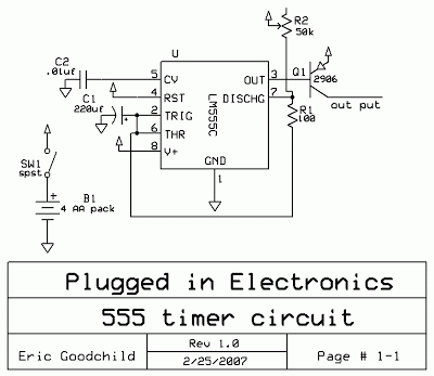
simple 555 timer circuit
This is a simple 555 timer circuit suitable for oscillating applications. To slow down the strobe effect, replace the 220 µF capacitors with 1000 µF capacitors. For a faster strobe effect, use a 150 µF capacitor. Additionally, R1 can be...
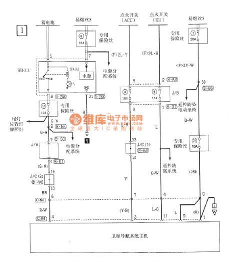
Serial DRAM non voltizer
This device includes a ringing generator and a tone oscillator. The tone oscillator is configured to operate at either 350 Hz or 440 Hz. The ringing generator is a sealed module providing 86 Vac at 20 Hz. Upon application of...

power amp acoustic
Circuit diagram of marine TV dish. Circuit diagram of marine TV dish, circuit diagram of marine TV dish, 12V DC to 120V AC inverter circuit diagram PDF, 12V DC to 120V AC inverter circuit diagram PDF.
The circuit diagram for a...

Simple optical switch circuit
The 555 timer is recognized as one of the most versatile and widely used integrated circuits globally. One of its potential applications is as a simple inverting Schmitt trigger.
The 555 timer can be configured in various modes, including monostable, astable,...

555 Timer as an Astable Multivibrator
An astable multivibrator, often referred to as a free-running multivibrator, is a rectangular-wave generating circuit. Unlike the monostable multivibrator, this circuit does not require any external trigger to change the state of the output, hence the term free-running. Before constructing...
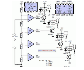
Reducing Relay Power Consumption
This circuit demonstrates that microprocessors, personal computers, and the latest ultra-accurate digital-to-analog converters (DACs) are excessive for the task of sequentially controlling four relays.
The circuit utilizes a simple microcontroller or a basic timer IC to manage the operation of four...

Laser Activated Switch
This circuit is designed around a 555 timer and utilizes very few components. Its simplicity allows even novices to construct and use it as a control device. A laser pointer, widely available in the market, can be employed to operate...