


Simple Schmitt Trigger Circuit

Description: A 555 IC is configured to function as a Schmitt trigger. Inputs above and below the threshold level will turn the circuit on and off, producing a square wave output.
The 555 timer integrated circuit (IC) is a versatile device commonly used in various applications, including oscillators, timers, and pulse generators. When configured as a Schmitt trigger, the 555 IC utilizes its internal comparators to provide hysteresis, allowing for clean switching between high and low output states in response to varying input signals.
In this configuration, the 555 timer operates in astable mode, where it continuously switches between its high and low states, generating a square wave output. The circuit includes two threshold levels: the upper threshold (2/3 Vcc) and the lower threshold (1/3 Vcc), which determine the switching points of the output. When the input voltage exceeds the upper threshold, the output switches to a low state, and when it falls below the lower threshold, the output returns to a high state. This hysteresis effect reduces the likelihood of false triggering caused by noise or fluctuations in the input signal.
The timing components, typically resistors and capacitors, are crucial in defining the frequency and duty cycle of the output waveform. The relationship between these components can be calculated using standard formulas, allowing for precise control over the output characteristics. The output of the 555 Schmitt trigger can be used to drive various loads, such as LEDs, transistors, or other digital circuits, making it an essential building block in electronic design.
Overall, the 555 IC configured as a Schmitt trigger is an effective solution for applications requiring reliable signal conditioning and waveform generation. A 555 IC is shown configured to function as a Schmitt trigger. Inputs above and below the threshold level will turn the circuit on and off producing a square wave output.
The 555 timer integrated circuit (IC) is a versatile device commonly used in various applications, including oscillators, timers, and pulse generators. When configured as a Schmitt trigger, the 555 IC utilizes its internal comparators to provide hysteresis, allowing for clean switching between high and low output states in response to varying input signals.
In this configuration, the 555 timer operates in astable mode, where it continuously switches between its high and low states, generating a square wave output. The circuit includes two threshold levels: the upper threshold (2/3 Vcc) and the lower threshold (1/3 Vcc), which determine the switching points of the output. When the input voltage exceeds the upper threshold, the output switches to a low state, and when it falls below the lower threshold, the output returns to a high state. This hysteresis effect reduces the likelihood of false triggering caused by noise or fluctuations in the input signal.
The timing components, typically resistors and capacitors, are crucial in defining the frequency and duty cycle of the output waveform. The relationship between these components can be calculated using standard formulas, allowing for precise control over the output characteristics. The output of the 555 Schmitt trigger can be used to drive various loads, such as LEDs, transistors, or other digital circuits, making it an essential building block in electronic design.
Overall, the 555 IC configured as a Schmitt trigger is an effective solution for applications requiring reliable signal conditioning and waveform generation. A 555 IC is shown configured to function as a Schmitt trigger. Inputs above and below the threshold level will turn the circuit on and off producing a square wave output.
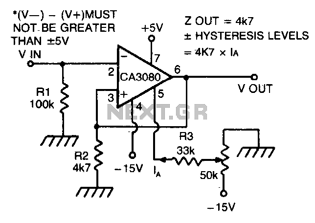
Schmitt trigger with programmable hysteresis
The CA 3088 is utilized as a versatile Schmitt trigger. The magnitude of the hysteresis levels is determined by the current (Ia) flowing out of the amplifier's output and through resistor R2. An increase in Ia results in an increase...
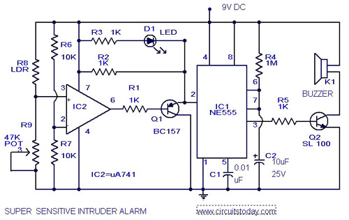
Sensitive Intruder AlarmCircuit using 555 IC and 741 IC
The circuit diagram represents an ultra-sensitive intruder alarm. A shadow from an intruder passing nearby is sufficient to trigger the alarm. The operational amplifier IC2 (uA 741) is configured as a sensitive comparator, with its set point determined by resistors...
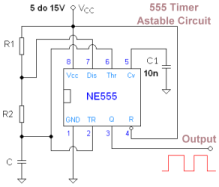
555 IC Square Wave Oscillator circuit
A type of relaxation oscillator comprising two stages that are interconnected such that the input of one stage is derived from the output of the other. This configuration essentially consists of two amplifiers cross-coupled with regenerative feedback in its simplest...

Temperature Controller with 555 Circuit
Construct a temperature controller circuit using the 555 integrated circuit (IC) in combination with a thermistor resistor divider. The benefit of this design is that it does not require a well-regulated power supply. The resistor divider network comprises an adjustable...

Touch Switch Monostable/Timer with 555 IC
Utilizing the specified values depicted in the schematic diagram, this circuit features a timed ON period of 4 seconds. The ON time is governed by the values of capacitor C2 and resistor R3; increasing either C2 or R3 will extend...

Simple Analogue Electronic Key
This circuit utilizes two comparators configured as a window comparator. Resistors R2, R5, and R10 establish a voltage window within which the voltage at the junction of D2 and D6 must reside for the outputs of IC2.A and IC2.B to...

The reference voltage of the symmetrical bipolar comparator
An AI comparator input is connected to a reference resistor (Rl). When the output reaches a specified level, known as VREP (absolute value), the output also stabilizes at this level. The outputs Ai and As are connected to an OR...

Output by the CS3843 and CS5101 composed of 5V 3.3V switching DC power supply circuit
The CS3843 and CS5101 are components of a 5V/3.3V switching DC power supply circuit. The CS3843 is a fixed frequency PWM controller characterized by a set oscillator that precisely controls the duty cycle. It features a temperature-compensated reference voltage, a...

Schmitt Trigger Circuit
This Schmitt trigger circuit is emitter coupled and provides a simple comparator action. The 2N3069 JFET places very little loading on the measured input. Schmitt trigger, emitter coupled, simple comparator, 2N3565, distinct hysteresis loop.
The described circuit utilizes an emitter-coupled Schmitt...