


Switch Debouncing
#switch debouncing
#555 timer
#monostable
#push button
#contact bounce
#transient spikes
#SPDT
#PBS
#pulse generation

Description: This circuit will remove the transient spikes and contact bounces from a non-latching push button switch. Using a 555 timer as a monostable circuit, it is easy to build a good switch debouncer circuit. There are many circuits for SPDT debouncing, but not many for a normally open, push-to-make press button switch (PBS). The 555 monostable gives an output pulse of around 20 msec with component values shown. More: The 555 circuit can be re-triggered if the input is held low longer than the output pulse. To prevent this happening, I have included a further timing circuit comprised of the 1Meg resistor and 47n capacitor. Normally, the 47n capacitor is discharged via
The described circuit employs a 555 timer in a monostable configuration to effectively debounce a normally open push button switch (PBS). The primary function of this circuit is to eliminate unwanted transient spikes and contact bounce that may occur when the switch is pressed or released. In this setup, the 555 timer generates a single output pulse of approximately 20 milliseconds whenever the push button is activated.
The circuit's design includes a timing component that ensures the output pulse duration can be adjusted by changing the resistor and capacitor values connected to the 555 timer. The output pulse duration is crucial for ensuring that any mechanical bouncing of the switch contacts does not result in multiple unwanted pulses being registered in the connected circuitry.
To further enhance the reliability of the debouncing mechanism, a secondary timing circuit is integrated, consisting of a 1 Megohm resistor and a 47 nanofarad capacitor. This additional timing circuit serves to prevent the 555 timer from being retriggered while the input remains low longer than the output pulse. When the push button is pressed, the capacitor charges through the resistor, and this RC time constant helps to ensure that the timer output remains stable and is not inadvertently retriggered by continued contact bounce.
In summary, this circuit configuration provides a robust solution for debouncing a push button switch, making it highly suitable for applications where precise switch activation is critical. The use of the 555 timer in monostable mode, combined with the additional timing elements, ensures that the output remains clean and free from noise, thereby improving the overall performance and reliability of the electronic system in which it is implemented.This circuit will remove the transient spikes and contact bounces from a non-latching push button switch. Using a 555 timer as a monostable circuit, it is easy to build a good switch debouncer circuit. There are many circuits for SPDT debouncing, but not many for a normally open, push-to-make press button switch (PBS).
The 555 monostable gives an output pulse of around 20 msec with component values shown. The 555 circuit can be re-triggered if the input is held low longer than the output pulse. To prevent this happening, I have included a further timing circuit comprised of the 1Meg resistor and 47n capacitor. Normally, the 47n capacitor is discharged via
The described circuit employs a 555 timer in a monostable configuration to effectively debounce a normally open push button switch (PBS). The primary function of this circuit is to eliminate unwanted transient spikes and contact bounce that may occur when the switch is pressed or released. In this setup, the 555 timer generates a single output pulse of approximately 20 milliseconds whenever the push button is activated.
The circuit's design includes a timing component that ensures the output pulse duration can be adjusted by changing the resistor and capacitor values connected to the 555 timer. The output pulse duration is crucial for ensuring that any mechanical bouncing of the switch contacts does not result in multiple unwanted pulses being registered in the connected circuitry.
To further enhance the reliability of the debouncing mechanism, a secondary timing circuit is integrated, consisting of a 1 Megohm resistor and a 47 nanofarad capacitor. This additional timing circuit serves to prevent the 555 timer from being retriggered while the input remains low longer than the output pulse. When the push button is pressed, the capacitor charges through the resistor, and this RC time constant helps to ensure that the timer output remains stable and is not inadvertently retriggered by continued contact bounce.
In summary, this circuit configuration provides a robust solution for debouncing a push button switch, making it highly suitable for applications where precise switch activation is critical. The use of the 555 timer in monostable mode, combined with the additional timing elements, ensures that the output remains clean and free from noise, thereby improving the overall performance and reliability of the electronic system in which it is implemented.This circuit will remove the transient spikes and contact bounces from a non-latching push button switch. Using a 555 timer as a monostable circuit, it is easy to build a good switch debouncer circuit. There are many circuits for SPDT debouncing, but not many for a normally open, push-to-make press button switch (PBS).
The 555 monostable gives an output pulse of around 20 msec with component values shown. The 555 circuit can be re-triggered if the input is held low longer than the output pulse. To prevent this happening, I have included a further timing circuit comprised of the 1Meg resistor and 47n capacitor. Normally, the 47n capacitor is discharged via

9 Second Digital Readout Countdown Timer
This circuit provides a visual 9-second delay using a 7-segment digital readout LED. When the switch is closed, the CD4010 up/down counter is preset to 9, and the 555 timer is disabled with the output held high. When the switch...
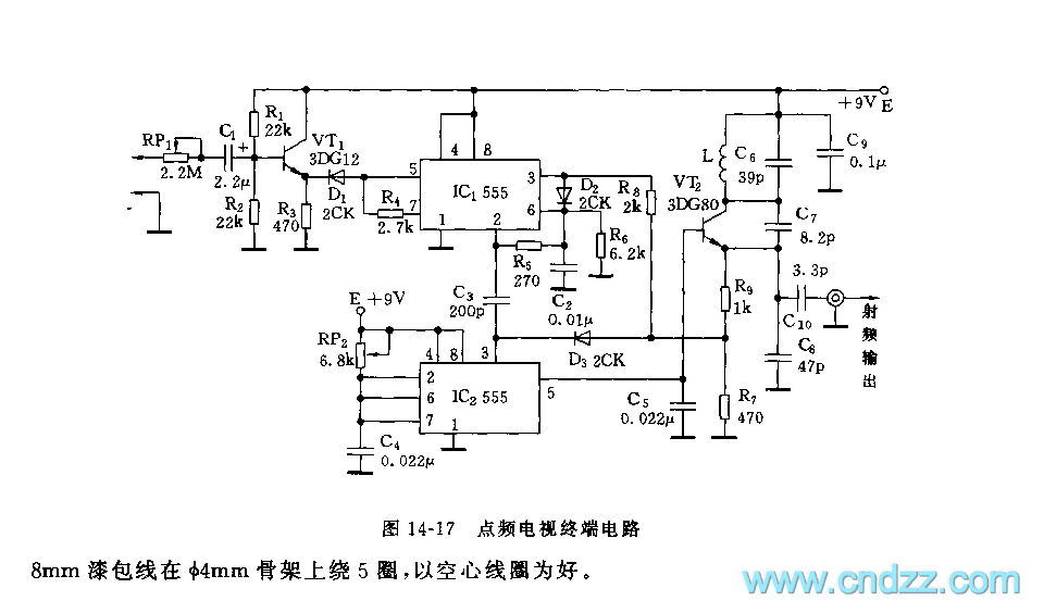
555 point-frequency TV terminal circuit
As shown in figure 14-17, this circuit consists of the input circuit, the line frequency synchronization generator, the sample-and-hold circuit, the voltage control delay generator, and the RF modulator. The input circuit includes the input attenuator RP1 and the emitter...

Headlight Flasher Circuit
The headlight flasher is a 555 oscillator/timer configured as an astable multivibrator (oscillator). Its input is used to drive the gate of an IRF53IND hexFET, which acts as an on/off switch, turning the lamp on and off at an oscillating...

sound generator
The circuit described operates in astable mode using a 555 timer. Instead of a fixed resistor, a Light Dependent Resistor (LDR) is utilized to provide variable resistance for the 555 timer's operation in astable mode. As the resistance of the...

Invert a 555 Astable Output Signal
A variable frequency, variably duty cycle 555 configuration is set up in astable mode. A set of potentiometers is utilized to achieve a wide range of control. The output is functioning well; however, there is an issue. The circuit drives...

555 audio oscillator circuit diagram of a radio-frequency drive
The circuit features a 555 timer integrated circuit along with components R1, RP1, C1, and others, which together form an audio oscillator. The frequency of the oscillator is determined by the formula f = 1.44 / ((R1 + 2 *...

555 based Voltage inverter Schematic
This circuit converts a positive voltage to a negative voltage, resulting in a loss of approximately 1.5 V. For instance, supplying 9 V to the circuit yields an output of -7.5 V. Additionally, this circuit can function as a voltage...

555 jewelry small electronic circuit diagram
The circuit consists of a 555 timer and a light-emitting diode (LED) array. The 555 timer, along with resistors R1, R2, and capacitor C1, forms an astable multivibrator configuration. The oscillation frequency is calculated using the formula f = 1.44...

Multivibrator circuit
The 555 timer integrated circuit (IC) is an exceptionally versatile component utilized in various applications, including generating clock pulses, switch debouncing, and functioning as an output transducer. The standard 555 IC is packaged in an 8-pin configuration, available in Dual...