


The One-shot Monostable Multivibrator Circuit
#monostable
#multivibrator
#pulse generator
#one-shot
#timing circuit
#electronics tutorial
#waveform generation
#digital circuits

Description: Electronics tutorial about the monostable multivibrator circuit, also known as a one-shot monostable multivibrator, used as a pulse generator circuit.
The monostable multivibrator is a crucial component in electronic circuits, functioning as a pulse generator that produces a single output pulse in response to a triggering input. This circuit is characterized by its ability to return to a stable state after a temporary output pulse, hence the term "monostable."
The typical configuration of a monostable multivibrator involves a timing resistor (R) and a timing capacitor (C) connected to a trigger input. When the circuit is triggered, the capacitor charges through the resistor, and the output pulse width is determined by the RC time constant, calculated using the formula \( T = 1.1 \times R \times C \), where \( T \) is the duration of the output pulse in seconds.
Commonly, the 555 timer IC is utilized to construct monostable multivibrators due to its versatility and ease of use. In this configuration, the trigger input is connected to pin 2 of the 555 timer, while the timing components are connected between pin 6 (threshold) and pin 3 (output). The output pulse can be used in various applications, such as debounce circuits, timers, and pulse width modulation.
In practical applications, the monostable multivibrator can be employed to generate precise timing intervals for various electronic devices, ensuring accurate signal processing and control. Its simplicity and reliability make it an essential tool for engineers and hobbyists in the field of electronics.Electronics Tutorial about the Monostable Multivibrator Circuit also known as a One-shot Monostable Multivibrator used as a Pulse Generator Circuit..
The monostable multivibrator is a crucial component in electronic circuits, functioning as a pulse generator that produces a single output pulse in response to a triggering input. This circuit is characterized by its ability to return to a stable state after a temporary output pulse, hence the term "monostable."
The typical configuration of a monostable multivibrator involves a timing resistor (R) and a timing capacitor (C) connected to a trigger input. When the circuit is triggered, the capacitor charges through the resistor, and the output pulse width is determined by the RC time constant, calculated using the formula \( T = 1.1 \times R \times C \), where \( T \) is the duration of the output pulse in seconds.
Commonly, the 555 timer IC is utilized to construct monostable multivibrators due to its versatility and ease of use. In this configuration, the trigger input is connected to pin 2 of the 555 timer, while the timing components are connected between pin 6 (threshold) and pin 3 (output). The output pulse can be used in various applications, such as debounce circuits, timers, and pulse width modulation.
In practical applications, the monostable multivibrator can be employed to generate precise timing intervals for various electronic devices, ensuring accurate signal processing and control. Its simplicity and reliability make it an essential tool for engineers and hobbyists in the field of electronics.Electronics Tutorial about the Monostable Multivibrator Circuit also known as a One-shot Monostable Multivibrator used as a Pulse Generator Circuit..

About Area 50
This circuit divides a 10 MHz reference signal to produce outputs of 1, 10, 100, or 1000 pulses per second. The pulse width can be selected using jumpers, offering multiple options. A synchronization input aligns the output pulses with an...
Digital Circuits
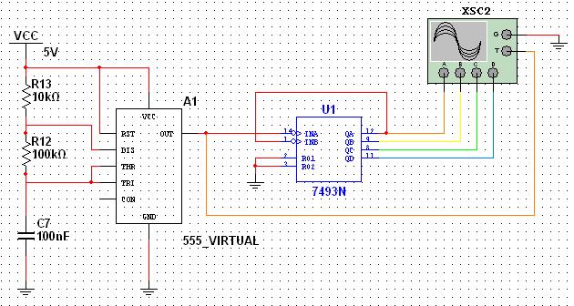
This tutorial explores a common digital concept using the NI Multisim software environment. It examines a four-bit counter that uses a 555 timer IC to generate the clock signal. This tutorial takes less than 30 minutes to complete and consists...

Turn an old PC into a multi-channel pulse generator, for PWM/servo/stepper
PulsePar turns a PC into a multi-channel pulse generator utilizing the parallel port. The period, duty and phase of each channel are adjustable so as to be used in PWM systems as well as in testing servo and stepper (stepping)...

Astable and Monostable Multivibrators
Multivibrators are two-state devices that are extensively used in digital electronics. Bistable multivibrators, also known as flip-flops, serve as fundamental memory elements.
Multivibrators can be categorized into three primary types: astable, monostable, and bistable. Each type has distinct operational characteristics and...

multivibrator astable
The astable multivibrator is a specific type of relaxation oscillator that utilizes in-phase feedback provided by a separate transistor. Initially constructed using vacuum tubes, this circuit gained widespread popularity and was extensively utilized in early computers and television sets for...

Pulse Signal Generator
The volt-ampere characteristics of a tunnel diode exhibit an S-shaped curve. The peak current point, referred to as point P, represents the maximum current, while the valley point, denoted as point V, indicates the minimum current. Key parameters of the...

MC CONTROL TRANSMITTER
A free-running multivibrator activates power amplifier Q4 for audio applications. The operational range is approximately 1 mile, and capacitor C6 is used to tune the collector of the oscillator to the crystal frequency. - Texas Instruments Inc., "Transistor Circuit Design,"...

Single pulse signal generating circuit
A single pulse signal generating circuit is depicted, which utilizes switch contacts to create a digital signal for reset or stop functions. This one-shot pulse generating circuit operates as a non-synchronous differential circuit.
The single pulse signal generating circuit, commonly referred...

Controlled pulse signal generating circuit
The circuit generates a controlled pulse signal. When a high pulse signal is applied to the input terminal O (start), the output pulse signal is activated. Conversely, when a low signal is received at the input terminal O (stop), the...