


timer Simple Metronome Circuit w/ Linear Pot Control
#metronome
#timer
#potentiometer
#BPM control
#pulse generator
#music
#timing circuit
#linear pot
#oscillator
#period control

Description: The typical BPM range for music is between 40 and 240 BPM, corresponding to periods of 1500 ms and 200 ms, respectively. A BPM of 120 equates to a period of 500 ms. The circuit requires a resistor R4 of 14.5 MΩ to achieve a period of 500 ms (120 BPM). A desired value of 5 kΩ (using a 10 kΩ potentiometer at the center position) is specified. Additionally, a configuration of parallel transistors provides a 4:1 step-down current mirror, allowing for smaller resistor values. This setup also establishes the control current relative to ground, which is advantageous depending on the power supply of the operational amplifier.
The circuit design revolves around generating a precise timing signal that corresponds to musical beats per minute (BPM). The operational amplifier (op-amp) is integral to this design, functioning as a comparator or amplifier that processes input signals to produce a clean output pulse. The timing is determined by the resistor-capacitor (RC) timing network, where the value of R4, when set to 14.5 MΩ, allows for the desired period of 500 ms to achieve a BPM of 120.
To adjust the resistance to the specified 5 kΩ, a 10 kΩ potentiometer can be utilized, enabling fine-tuning of the resistance value. This flexibility is crucial in applications where precise timing is essential, such as in metronomes or electronic drum machines.
The inclusion of a parallel transistor configuration serves a dual purpose: it reduces the effective resistance seen by the timing network, allowing for smaller physical resistor sizes, and it creates a current mirror with a 4:1 ratio. This current mirror stabilizes the control current, ensuring that it remains consistent relative to ground. This characteristic is particularly beneficial in designs where the op-amp is powered by varying supply voltages, as it enhances performance stability and reliability.
Overall, the combination of a carefully chosen resistor value, a tuning potentiometer, and a sophisticated transistor arrangement results in a robust circuit capable of producing accurate timing signals for musical applications.To get the usual BPM range for music of between 40 and 240 BPM, that corresponds to periods of 1500 ms and 200 ms respectively. A BPM of 120 is exactly 500 ms. As it is, the circuit would require an R4 of 14. 5 Mohm to yield a period of 500 ms (120 BPM). I need the value to be exactly 5K (10K pot in the center position). Here`s another version. That string of parallel transistors provides a 4:1 ratio step-down current mirror so that resistors can be smaller. It also makes the control current relative to ground which is nice depending on how you power your op amp.
The circuit design revolves around generating a precise timing signal that corresponds to musical beats per minute (BPM). The operational amplifier (op-amp) is integral to this design, functioning as a comparator or amplifier that processes input signals to produce a clean output pulse. The timing is determined by the resistor-capacitor (RC) timing network, where the value of R4, when set to 14.5 MΩ, allows for the desired period of 500 ms to achieve a BPM of 120.
To adjust the resistance to the specified 5 kΩ, a 10 kΩ potentiometer can be utilized, enabling fine-tuning of the resistance value. This flexibility is crucial in applications where precise timing is essential, such as in metronomes or electronic drum machines.
The inclusion of a parallel transistor configuration serves a dual purpose: it reduces the effective resistance seen by the timing network, allowing for smaller physical resistor sizes, and it creates a current mirror with a 4:1 ratio. This current mirror stabilizes the control current, ensuring that it remains consistent relative to ground. This characteristic is particularly beneficial in designs where the op-amp is powered by varying supply voltages, as it enhances performance stability and reliability.
Overall, the combination of a carefully chosen resistor value, a tuning potentiometer, and a sophisticated transistor arrangement results in a robust circuit capable of producing accurate timing signals for musical applications.To get the usual BPM range for music of between 40 and 240 BPM, that corresponds to periods of 1500 ms and 200 ms respectively. A BPM of 120 is exactly 500 ms. As it is, the circuit would require an R4 of 14. 5 Mohm to yield a period of 500 ms (120 BPM). I need the value to be exactly 5K (10K pot in the center position). Here`s another version. That string of parallel transistors provides a 4:1 ratio step-down current mirror so that resistors can be smaller. It also makes the control current relative to ground which is nice depending on how you power your op amp.

4541 Timer Relay Circuit 0.3 second to 10 hours
To initiate the timing process, there are two options available: either connect the START point to ground (GND), in which case the timer activates when connected to the voltage supply, or employ a switch to start the timer.
The timing circuit...

headlights timer
This device is a simple timer that keeps the headlights of a vehicle illuminated for approximately 1 minute and 30 seconds. This feature is particularly useful when accessing dark areas, eliminating the need to return to manually switch off the...

The switch shut off time delay circuit diagram
The switch shut-off time delay circuit consists of a timer, optocouplers, a bridge SCR, and an SCR AC switch. When the control button is released, it allows the motor or other AC power to remain active for one hour. Upon...

Repeating Timer 5
This timer circuit operates only when the temperature exceeds a predetermined level. An alternative version, known as Repeating Timer No. 6, functions while the temperature is below this preset level. The resistor R7 is used to set the temperature threshold....

The Ecology of the Oscillator Transmitter
An oscillator-only transmitter appears to be the simplest way to access the radio airwaves; however, it presents several challenges as part of a transmitting and receiving station. The issue of finding an adequate crystal-controlled transmitter for newcomers wishing to operate...

timer control 1 15 minutes by triac 2n6075 and lm555 lm358
Most timer circuits are often used with electrical transformers operating at low voltages such as 9V and 12V, and they incorporate electrical control relays. The timer can be set for durations ranging from 1 to 15 minutes.
Timer circuits are essential...

Repeating Timer 4
This circuit is the inverse of Repeating Timer No. 3. Its operation can be restricted to nighttime hours. The variable resistor (preset) allows selection of the darkness level at which the timer will activate.
The described circuit functions as a light-activated...
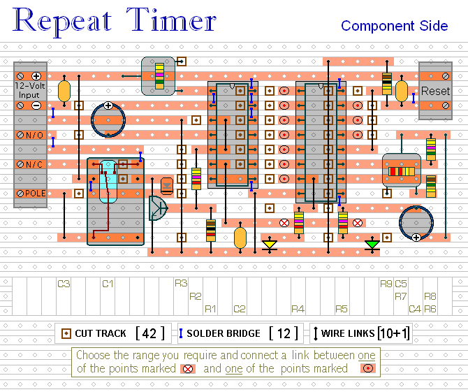
repeating interval timer
This circuit features an adjustable output timer that can re-trigger at specified intervals. The output duration can range from a fraction of a second to over half an hour, with the ability to repeat at consistent intervals from seconds to...

Oscillator-clock-generator
This self-starting fixed-frequency oscillator circuit provides excellent frequency stability. R1 and C1 form the frequency-determining network, while R2 delivers the regenerative feedback. Diode D1 improves stability by compensating for the difference between VaH and VsurrLY. In applications where a precision...