


Ua2240-staircase-generator
#uA2240
#staircase generator
#timer
#counter
#resistor ladder
#op amp
#astable mode
#trigger pulse
#time base oscillator

Description: The uA2240 timer/counter, in conjunction with a precision resistor ladder network and an operational amplifier, creates a staircase generator. In astable mode, the uA2240 operates continuously after a trigger pulse is applied until it receives a reset pulse. The trigger input at pin 11 is connected to the time base output at pin 14, facilitating automatic start and continuous operation. The frequency of the time-base oscillator (TBO) is determined by the time constants R1 and C1, calculated as f = 1/(R1*C1). In this example, a 10 kΩ resistor and a 0.01 µF capacitor form the timing network. The counter outputs are linked to a precision resistor ladder network featuring binary-weighted resistors. The current sink through these resistors corresponds to the count number. For instance, the current sink at Q7, the most significant bit, is 128 times that of Q0, the least significant bit. As the uA2240 generates an eight-bit count, the current sink through each active binary-weighted resistor reduces the positive output of the operational amplifier in discrete steps. A feedback potentiometer is set to a nominal 10 kΩ to provide a maximum output voltage range. With a 12 V input, a 10 V output swing is achievable. When a 0.5 V reference is applied to pin 3 of the TCL271, the output transitions from a maximum of 10.46 V in 256 steps of 38.9 mV per step to a minimum of 0.5 V. Each step has a pulse duration of 100 µs and an amplitude reduction of 38.9 mV. The output waveform is repeated until a reset is applied to the uA2240.
The uA2240 serves as a versatile timer and counter, capable of generating precise timing signals for various applications. Its integration with a precision resistor ladder allows for accurate voltage levels to be produced, which can be essential in digital-to-analog conversion tasks. The resistor ladder network's binary-weighted configuration ensures that each output bit contributes proportionally to the output voltage, enabling smooth transitions between voltage levels.
In practical applications, the choice of the timing components R1 and C1 is critical, as they directly influence the frequency of the staircase waveform generated. The selected values of 10 kΩ and 0.01 µF yield a frequency of 1 kHz, making it suitable for audio applications or other timing-related tasks that require a stable output.
The operational amplifier used in conjunction with the uA2240 and the resistor ladder is responsible for amplifying the voltage output to a usable level. The feedback potentiometer allows for fine-tuning of the output range, accommodating various input voltage levels while ensuring that the output remains within desired limits. The ability to set a reference voltage at pin 3 of the TCL271 enables precise control over the output behavior, making this configuration adaptable to a wide range of scenarios.
The staircase waveform generated by this circuit can be employed in applications such as signal modulation, digital signal processing, and waveform generation. The discrete steps of 38.9 mV provide a high level of granularity, which can be beneficial in applications requiring fine control over voltage levels. The pulse duration of 100 µs indicates that the output can be utilized in high-speed applications where timing accuracy is paramount. Overall, the combination of the uA2240 timer/counter, precision resistor ladder, and operational amplifier creates a highly effective staircase generator circuit.The uA2240 timer/counter, combined with aprecision resistor ladder network and an op amp, form the staircase generator. In the astable mode, once a trigger pulse is applied, the uA2240 operates continuously until it receives a reset pulse.
The trigger input at pin 11 is tied to the time base output at pin 14, resulting in automatic starting and continuous operation. The frequency of the time-base oscillator, TBO, is set by the time constants R1 and C1 (f = 1/RIC1).
For this example, a 10-KO resistor and a 0.01-I"F capacitor form the timing network. The counter outputs are connected to a precision resistor ladder network with binary-weighted resistors. The current sink through the resistors connectedJo the counter outputs correspond to the count number.
For example, the current sink at Q7, the most significant bit, is 128 times the current sink at QO, the least significant bit. As the count is generated by the uA2240 eight-bit counter, the current sink through each active binary-weighted resistor decreases thepositive output of the op amp in discrete steps.
The feedback potentiometer is set at a nominal10 K{l to supply a maximum output voltage range. An input of 12 V allows a 10-V output swing. With a 0. 5-V input reference on pin 3 of the TCL271, the output will change from 10.46 V maximum, in 256 steps of 38.9 mV per step, to a 0.5 V minimum. Each step has a pulse duration of 100 l"s and an amplitude decrease of 38.9 mV. The waveform output is repeated until a reset is applied to the uA2240.
The uA2240 serves as a versatile timer and counter, capable of generating precise timing signals for various applications. Its integration with a precision resistor ladder allows for accurate voltage levels to be produced, which can be essential in digital-to-analog conversion tasks. The resistor ladder network's binary-weighted configuration ensures that each output bit contributes proportionally to the output voltage, enabling smooth transitions between voltage levels.
In practical applications, the choice of the timing components R1 and C1 is critical, as they directly influence the frequency of the staircase waveform generated. The selected values of 10 kΩ and 0.01 µF yield a frequency of 1 kHz, making it suitable for audio applications or other timing-related tasks that require a stable output.
The operational amplifier used in conjunction with the uA2240 and the resistor ladder is responsible for amplifying the voltage output to a usable level. The feedback potentiometer allows for fine-tuning of the output range, accommodating various input voltage levels while ensuring that the output remains within desired limits. The ability to set a reference voltage at pin 3 of the TCL271 enables precise control over the output behavior, making this configuration adaptable to a wide range of scenarios.
The staircase waveform generated by this circuit can be employed in applications such as signal modulation, digital signal processing, and waveform generation. The discrete steps of 38.9 mV provide a high level of granularity, which can be beneficial in applications requiring fine control over voltage levels. The pulse duration of 100 µs indicates that the output can be utilized in high-speed applications where timing accuracy is paramount. Overall, the combination of the uA2240 timer/counter, precision resistor ladder, and operational amplifier creates a highly effective staircase generator circuit.The uA2240 timer/counter, combined with aprecision resistor ladder network and an op amp, form the staircase generator. In the astable mode, once a trigger pulse is applied, the uA2240 operates continuously until it receives a reset pulse.
The trigger input at pin 11 is tied to the time base output at pin 14, resulting in automatic starting and continuous operation. The frequency of the time-base oscillator, TBO, is set by the time constants R1 and C1 (f = 1/RIC1).
For this example, a 10-KO resistor and a 0.01-I"F capacitor form the timing network. The counter outputs are connected to a precision resistor ladder network with binary-weighted resistors. The current sink through the resistors connectedJo the counter outputs correspond to the count number.
For example, the current sink at Q7, the most significant bit, is 128 times the current sink at QO, the least significant bit. As the count is generated by the uA2240 eight-bit counter, the current sink through each active binary-weighted resistor decreases thepositive output of the op amp in discrete steps.
The feedback potentiometer is set at a nominal10 K{l to supply a maximum output voltage range. An input of 12 V allows a 10-V output swing. With a 0. 5-V input reference on pin 3 of the TCL271, the output will change from 10.46 V maximum, in 256 steps of 38.9 mV per step, to a 0.5 V minimum. Each step has a pulse duration of 100 l"s and an amplitude decrease of 38.9 mV. The waveform output is repeated until a reset is applied to the uA2240.

Timer Garage Door Circuit Schematic Diagram
Timer garage door circuit schematic diagram, printed circuit board.
The timer garage door circuit is designed to automate the opening and closing of a garage door based on a predetermined time interval. The schematic diagram illustrates the layout and connections of...

Coin Counter circuit
The next counter section operates similarly but is designed to count four quarters, single $1 coins (loonies), and single $2 coins (toonies). The circuit for the toonies is configured.
The circuit for the counter section includes a digital counting mechanism that...
input impedance booster circuit
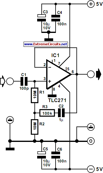
The input impedance of AC-coupled operational amplifier (op-amp) circuits is primarily determined by the resistance that establishes the DC operating point. When using CMOS op-amps, the input impedance is high, reaching up to 10 MΩ in current op-amps. For applications...

A Light Operated Repeating Timer Circuit
This circuit closely resembles Repeating Timer No. 2. However, the inclusion of a light-dependent resistor (LDR) allows the timer's operation to be confined to daylight hours. Resistor R7 enables the adjustment of the light level at which the timer will...

APPLIANCE CONTROL USING TIMER - PROJECT
This document presents an electronic project focused on device control using a timer. This circuit allows for the activation of an appliance at a specified time for a predetermined duration. It can be applied to manage the operation of systems...

Electronic counter with automatic counting interface circuit a
An electronic calculator features an automatic counting interface circuit, as illustrated in the accompanying figures. Figure (a) depicts a stroke switch controlled via optocoupler B. Figure (b) shows the application of a reed switch (KR) for pulse control signals. Figure...

Long-term electronic timer
The timer consists of an oscillator and a counter integrated into a single circuit. The timing interval is calculated by multiplying the oscillator period by the number of cycles to be counted. The frequency of the oscillator is influenced by...

The switch shut off time delay circuit diagram
The switch shut-off time delay circuit consists of a timer, optocouplers, a bridge SCR, and an SCR AC switch. When the control button is released, it allows the motor or other AC power to remain active for one hour. Upon...

Subcarrier Adapter For Fm Tuners Circuit
The operational amplifier (Op Amp) U1 and its associated components form a 67-kHz bandpass filter. A twin-T network, consisting of four 1100-ohm resistors and four 0.0022-microfarad capacitors, is integrated into the feedback loop of the op amp. This configuration provides...