


2 LED flasher with two 2N3904 transistors
#LED flasher
#2N3904
#astable multivibrator
#transistor
#flashing circuit
#current limiting
#resistor
#LED brightness
#simple circuit

Description: This is a simple LED flasher using two 2N3904 transistors. Classic astable multivibrator using 2 transistors. Transistor is not critical. Try these: 2N4401, 2N2222, NTE123A, NTE123AP, NTE159, TUP/TUN and those in your junk box, you may find that most of them will work. Obviously, the 470 ohm resistor determines the LED's brightness and limits the current flow to about 20mA. 390 ohm can also be used as a save value. If you decide to go with a green or yellow led, which draw more current, you may want to replace the 470 ohm with 270 or 330 ohm values. Flash rate is determined by the 39K resistors and the 10µF capacitors (determines the 'ON' time). The two sides do not have to match. Different values for each side can give a nice effect for unique duty-cycles. Flashrate for above circuit is 1 cycle per second.
The described circuit is an astable multivibrator configuration utilizing two 2N3904 NPN transistors, which are fundamental components for creating a simple LED flasher. This circuit operates continuously in a toggling manner, causing the LED to flash at a predetermined rate. The choice of transistors is flexible; other NPN transistors such as 2N4401, 2N2222, NTE123A, NTE123AP, and NTE159 can also be employed, allowing for experimentation with various transistor types available in a typical electronics toolkit.
In this configuration, the 470-ohm resistor plays a crucial role in limiting the current flowing through the LED, ensuring it operates safely at approximately 20mA. An alternate resistor value of 390 ohms can be used as a substitute, providing a slight variation in brightness. If a green or yellow LED is utilized, which typically requires a higher current, it is advisable to adjust the resistor value to 270 or 330 ohms to accommodate the increased current demand and maintain appropriate brightness levels.
The flash rate of the LED is regulated by the resistor-capacitor (RC) network formed by the 39K resistors and the 10µF capacitors. The time constant of this network dictates the duration of the 'ON' state of the LED. Notably, the two halves of the circuit—each consisting of one transistor, a resistor, and a capacitor—do not need to be identical. By varying the resistor and capacitor values on either side, unique duty cycles can be achieved, resulting in varied flashing patterns and effects.
The typical flash rate for this circuit is approximately one cycle per second, but this can be adjusted by modifying the resistor and capacitor values, providing further flexibility in the design. This simple yet effective LED flasher circuit is ideal for various applications, including visual indicators, decorations, and educational demonstrations in basic electronics.This is a simple LED flasher using two 2N3904 transistors. Classic astable multivibrator using 2 transistors. Transistor is not critical. Try these: 2N4401, 2N2222, NTE123A, NTE123AP, NTE159, TUP/TUN and those in your junk box, you may find that most of them will work. Obviously, the 470 ohm resistor determines the LED's brightness and limits the current flow to about 20mA.
390 ohm can also be used as a save value. If you decide to go with a green or yellow led, which draw more current, you may want to replace the 470 ohm with 270 or 330 ohm values. Flash rate is determined by the 39K resistors and the 10µF capacitors (determines the 'ON' time). The two sides do not have to match. Different values for each side can give a nice effect for unique duty-cycles. Flashrate for above circuit is 1 cycle per second.
The described circuit is an astable multivibrator configuration utilizing two 2N3904 NPN transistors, which are fundamental components for creating a simple LED flasher. This circuit operates continuously in a toggling manner, causing the LED to flash at a predetermined rate. The choice of transistors is flexible; other NPN transistors such as 2N4401, 2N2222, NTE123A, NTE123AP, and NTE159 can also be employed, allowing for experimentation with various transistor types available in a typical electronics toolkit.
In this configuration, the 470-ohm resistor plays a crucial role in limiting the current flowing through the LED, ensuring it operates safely at approximately 20mA. An alternate resistor value of 390 ohms can be used as a substitute, providing a slight variation in brightness. If a green or yellow LED is utilized, which typically requires a higher current, it is advisable to adjust the resistor value to 270 or 330 ohms to accommodate the increased current demand and maintain appropriate brightness levels.
The flash rate of the LED is regulated by the resistor-capacitor (RC) network formed by the 39K resistors and the 10µF capacitors. The time constant of this network dictates the duration of the 'ON' state of the LED. Notably, the two halves of the circuit—each consisting of one transistor, a resistor, and a capacitor—do not need to be identical. By varying the resistor and capacitor values on either side, unique duty cycles can be achieved, resulting in varied flashing patterns and effects.
The typical flash rate for this circuit is approximately one cycle per second, but this can be adjusted by modifying the resistor and capacitor values, providing further flexibility in the design. This simple yet effective LED flasher circuit is ideal for various applications, including visual indicators, decorations, and educational demonstrations in basic electronics.This is a simple LED flasher using two 2N3904 transistors. Classic astable multivibrator using 2 transistors. Transistor is not critical. Try these: 2N4401, 2N2222, NTE123A, NTE123AP, NTE159, TUP/TUN and those in your junk box, you may find that most of them will work. Obviously, the 470 ohm resistor determines the LED's brightness and limits the current flow to about 20mA.
390 ohm can also be used as a save value. If you decide to go with a green or yellow led, which draw more current, you may want to replace the 470 ohm with 270 or 330 ohm values. Flash rate is determined by the 39K resistors and the 10µF capacitors (determines the 'ON' time). The two sides do not have to match. Different values for each side can give a nice effect for unique duty-cycles. Flashrate for above circuit is 1 cycle per second.

Common emitter amplifier input and output signals of the phase relationship
The common emitter amplifier circuit exhibits a specific phase relationship between its input and output signals. This configuration is widely utilized in various electronic devices primarily for its high voltage gain. However, the output impedance is higher than the input...
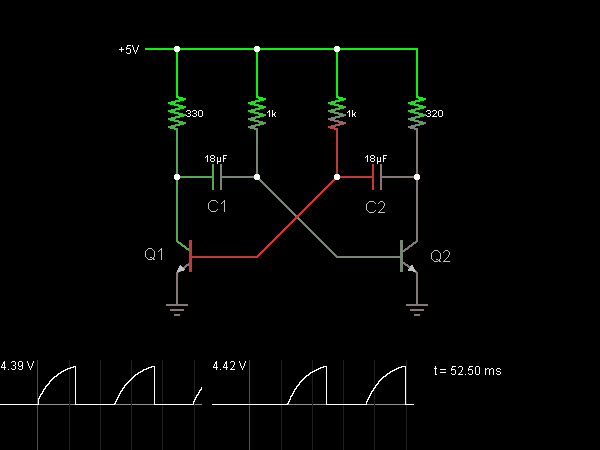
Astable Multivibrator (Oscillator)
This circuit functions as an astable multivibrator, also known as an oscillator. The two transistors are interconnected in a manner that allows the circuit to alternate between two states. In one state, the base of transistor Q1 is approximately one...
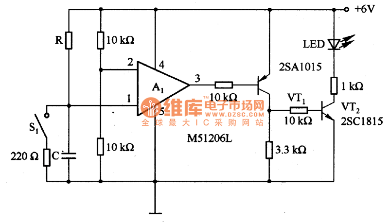
The time delay circuit diagram composed of transistor
The circuit is designed to set a delay time based on the voltage Us and the resistor R. In this configuration, S1 acts as the discharge switch for capacitor C. When switch S1 is closed, the stored charge in capacitor...

Camera flash circuit
A simple transistor generator and transformer converts a 1.5V battery voltage to several hundred volts. This high voltage current then passes through a diode, which rectifies the current to DC. This DC current is stored in a relatively large capacitor....

Simple preamplifier circuits by transistors
When there is a need to amplify audio signals from various sources before they reach a custom amplifier, a preamplifier (or preamp) is typically employed. This document suggests a specific circuit that is interesting due to its use of a...

Transistor Bistable Multivibrator or Flip-flop
Electronics tutorial about bistable multivibrator, also known as the bistable flip-flop or two-shot multivibrator, constructed from transistors or logic gates.
A bistable multivibrator is a fundamental electronic circuit that has two stable states and can maintain its state indefinitely until triggered...
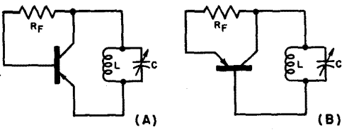
Fundamentals of Transistor Oscillators
This chapter discusses the operation and circuitry of transistor oscillators, which can be categorized into two types: feedback (similar to vacuum tube oscillators) and negative-resistance (current multiplying). Transistor oscillators can generate sine waves using various operational modes, including some novel...

Kapanadze 5
The emitter voltage drops completely to 0V from 42V during the pulse when the transistor is conducting or saturated. This contrasts with a pure resistive load (the 4.7 Ohm resistor mentioned in the previous video), where the collector-emitter voltage does...

Tickler oscillator circuit
When the circuit is initially powered, neither transistor is activated, resulting in high base voltages for both and a tendency to turn on. Due to slight asymmetries, one transistor will activate first, leading the circuit into one of its states...