


Transistor Checker with 555
#transistor checker
#555 timer
#flip-flop
#LED indicator
#testing circuit
#current limiting
#multi vibrator
#output power transistors

Description: This simple circuit has helped me out on many occasions. It is able to check transistors, in the circuit, down to 40 ohms across the collector-base or base-emitter junctions. It can also check the output power transistors on amplifier circuits. Circuit operation is as follows. The 555 timer (IC1) is set up as a 12Hz multivibrator. The output on pin 3 drives the 4027 flip-flop (IC2). This flip-flop divides the input frequency by two and delivers complementary voltage outputs to pin 15 and 14. The outputs are connected to LED1 and LED2 through the current limiting resistor R3. The LEDs are arranged so that when the polarity across the circuit is one way only one LED will light and when the polarity reverses the other LED will light, therefore when no transistor is connected to the tester the LEDs will alternately flash. The IC2 outputs are also connected to resistors R4 and R5 with the junction of these two resistors connected to the base of the transistor being tested. With a good transistor connected to the tester, the transistor will turn on and produce a short across the LED pair. If a good NPN transistor is connected then LED1 will flash by itself and if a good PNP transistor is connected then LED2 will flash by itself. If the transistor is open both LEDs will flash and if the transistor is shorted then neither LED will flash.
The circuit described is a transistor tester that utilizes a 555 timer integrated circuit (IC) and a dual flip-flop IC (4027) to provide a simple yet effective means to test NPN and PNP transistors. The 555 timer is configured in astable mode to generate a square wave output at approximately 12 Hz. This output is fed into the 4027 flip-flop, which serves to divide the frequency by two, resulting in complementary outputs that alternate between high and low states.
The outputs from the flip-flop are connected to two light-emitting diodes (LEDs), designated as LED1 and LED2, through a current-limiting resistor (R3). The arrangement of the LEDs is such that they are oriented in opposite polarities. When the circuit is powered without a transistor connected, both LEDs will blink alternately, indicating the circuit is functioning properly.
When a transistor is connected to the tester, the base of the transistor is linked to a junction formed by two additional resistors (R4 and R5). If a good NPN transistor is connected, it will allow current to flow, causing LED1 to illuminate consistently. Conversely, if a good PNP transistor is tested, LED2 will light up. In situations where the transistor is open (non-functional), both LEDs will flash, indicating a lack of conduction. If the transistor is shorted, both LEDs will remain off, signaling a fault condition.
This circuit provides a visual and straightforward method for testing transistors, making it an invaluable tool for electronics troubleshooting and repair. The use of common components such as the 555 timer and 4027 flip-flop ensures that the circuit is both cost-effective and easy to assemble.This simple circuit has helped me out on many occasions. It is able to check transistors, in the circuit, down to 40 ohms across the collector-base or base-emitter junctions. It can also check the output power transistors on amplifier circuits. Circuit operation is as follows. The 555 timer ( IC1 ) is set up as a 12hz multi vibrator. The output on pin 3 drives the 4027 flip-flop ( IC2). This flip-flop divides the input frequency by two and delivers complementary voltage outputs to pin 15 and 14.
The outputs are connected to LED1 and LED2 through the current limiting resistor R3. The LED's are arranged so that when the polarity across the circuit is one way only one LED will light and when the polarity reverses the other LED will light, therefore when no transistor is connected to the tester the LED's will alternately flash. The IC2 outputs are also connected to resistors R4 and R5 with the junction of these two resistors connected to the base of the transistor being tested. With a good transistor connected to the tester, the transistor will turn on and produce a short across the LED pair.
If a good NPN transistor is connected then LED1 will flash by itself and if a good PNP transistor is connected then LED2 will flash by itself. If the transistor is open both LED's will flash and if the transistor is shorted then neither LED will flash.
The circuit described is a transistor tester that utilizes a 555 timer integrated circuit (IC) and a dual flip-flop IC (4027) to provide a simple yet effective means to test NPN and PNP transistors. The 555 timer is configured in astable mode to generate a square wave output at approximately 12 Hz. This output is fed into the 4027 flip-flop, which serves to divide the frequency by two, resulting in complementary outputs that alternate between high and low states.
The outputs from the flip-flop are connected to two light-emitting diodes (LEDs), designated as LED1 and LED2, through a current-limiting resistor (R3). The arrangement of the LEDs is such that they are oriented in opposite polarities. When the circuit is powered without a transistor connected, both LEDs will blink alternately, indicating the circuit is functioning properly.
When a transistor is connected to the tester, the base of the transistor is linked to a junction formed by two additional resistors (R4 and R5). If a good NPN transistor is connected, it will allow current to flow, causing LED1 to illuminate consistently. Conversely, if a good PNP transistor is tested, LED2 will light up. In situations where the transistor is open (non-functional), both LEDs will flash, indicating a lack of conduction. If the transistor is shorted, both LEDs will remain off, signaling a fault condition.
This circuit provides a visual and straightforward method for testing transistors, making it an invaluable tool for electronics troubleshooting and repair. The use of common components such as the 555 timer and 4027 flip-flop ensures that the circuit is both cost-effective and easy to assemble.This simple circuit has helped me out on many occasions. It is able to check transistors, in the circuit, down to 40 ohms across the collector-base or base-emitter junctions. It can also check the output power transistors on amplifier circuits. Circuit operation is as follows. The 555 timer ( IC1 ) is set up as a 12hz multi vibrator. The output on pin 3 drives the 4027 flip-flop ( IC2). This flip-flop divides the input frequency by two and delivers complementary voltage outputs to pin 15 and 14.
The outputs are connected to LED1 and LED2 through the current limiting resistor R3. The LED's are arranged so that when the polarity across the circuit is one way only one LED will light and when the polarity reverses the other LED will light, therefore when no transistor is connected to the tester the LED's will alternately flash. The IC2 outputs are also connected to resistors R4 and R5 with the junction of these two resistors connected to the base of the transistor being tested. With a good transistor connected to the tester, the transistor will turn on and produce a short across the LED pair.
If a good NPN transistor is connected then LED1 will flash by itself and if a good PNP transistor is connected then LED2 will flash by itself. If the transistor is open both LED's will flash and if the transistor is shorted then neither LED will flash.

Spaceship Alarm Circuit
This circuit utilizes two 555 timers to generate a low-frequency tone that gradually increases to a high-frequency tone over the course of approximately 1 second. Following this, the sound ceases for about 0.3 seconds before the cycle begins anew. The...

Magnetic Gun
Pictured in Figure 1 is a miniature magnetic gun. When optimally tuned, it will propel a small slug about 1.5 metres high, or 2.5 metres horizontally. IC1 is a 555 timer in astable mode, sending approx. 10 ms pulses to...

flipflop What happens when theres no specific input variable on a logic diagram using a JK flip flop
Q1 and Q2 form a table. On the left side, list the four possible states of Q1 and Q2; on the right side, write the values that Q1 and Q2 will assume after the next clock pulse. The table will...
Digital Dice Project
This digital dice electronic project utilizes a combination of a 555 timer, a 7490 decade counter, a 7483 4-bit binary adder, a 7447 BCD to 7-segment decoder, and a 7-segment display to show the digit.
The digital dice project is designed...

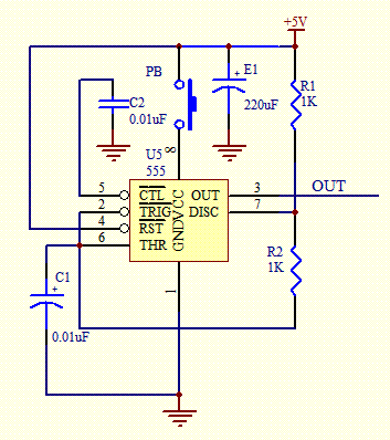
What is the purpose resistors and capacitor in this 555 circuit
It is a typical Astable Multivibrator (AMV) setup. The capacitor charges through both resistors until it reaches 2/3 of Vcc, which is the level of the internal comparator. This triggers a flip-flop, activating the Discharge output (DIS). The capacitor then...

Battery simulator provides current limiting
A constant-voltage active load can function as a battery during the charge cycle. The load voltage can be adjusted from 5 to 35V using potentiometer PV, simulating batteries with voltages ranging from 6 to 32V. In the testing of a...
LIGHT DIMMER
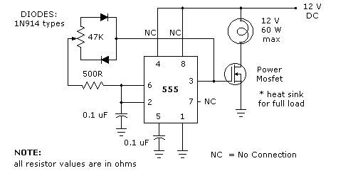
The 555 timer light dimmer schematic circuit is shown in figure 1 below. For the light dimmer to work, the 555 timer is configured as a variable cycle astable oscillator running somewhere around 300 Hz. The power MOSFET used here...

555 Timer Time Delay Circuit
The 555 Timer Time Delay Circuit uses LEDs to visually indicate the status of the circuit at any moment. The operation begins when the reset switch, SW2, is activated.
The 555 Timer is a versatile integrated circuit widely used for generating...
DC Voltage Doubler Circuit with 555
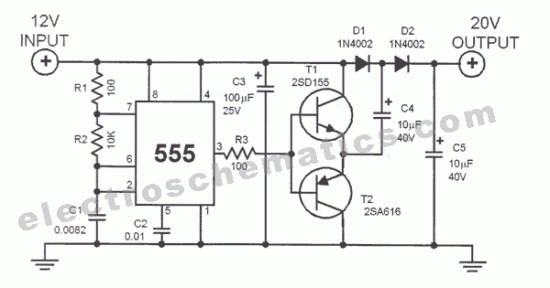
This DC voltage doubler circuit generates a voltage that is double its supply voltage. It is beneficial when a higher voltage level is required from a single power source.
The DC voltage doubler circuit typically employs a combination of capacitors and...