


Transistor Relay Driver Circuit
#relay
#driver circuit
#transistor
#switching
#chattering
#on/off
#electronics
#circuit design
#control

Description: One of the serious problems in relay-operated circuits is the relay clicking or chattering during the on/off operation of the relay driver transistor. This issue can lead to unreliable circuit performance and may cause premature wear of the relay contacts.
In relay-operated circuits, the phenomenon known as relay chattering occurs when the relay fails to maintain a stable state during the switching process. This instability is often caused by oscillations in the control signal driving the relay driver transistor. When the transistor is turned on or off, any noise or fluctuations in the control signal can cause the relay to rapidly switch between its on and off states, resulting in a clicking sound and potential damage to the relay contacts due to excessive wear.
To mitigate this issue, several strategies can be employed. One common solution involves adding a snubber circuit across the relay contacts to suppress voltage spikes that may occur during switching. Additionally, implementing a debounce circuit in the control signal path can help to filter out noise and ensure that only clean, stable signals are used to drive the relay.
Another approach is to utilize a relay driver circuit that incorporates hysteresis. By designing the driver with a small amount of positive feedback, the circuit can create a threshold that prevents the relay from toggling rapidly. This method stabilizes the on and off states, thus reducing chattering and enhancing the overall reliability of the circuit.
Furthermore, selecting a relay with appropriate specifications for the application, including contact ratings and response times, can also play a crucial role in minimizing chattering. Using solid-state relays can be advantageous as they typically do not exhibit the same mechanical wear as electromagnetic relays, thus providing a more reliable alternative for applications sensitive to such issues.
In summary, addressing the problem of relay chattering requires careful consideration of circuit design, component selection, and noise management to ensure stable operation and longevity of the relay system.One of the serious problems in relay operated circuits is the relay clicking or chattering during the on/off of the relay driver transistor. This problem i..
In relay-operated circuits, the phenomenon known as relay chattering occurs when the relay fails to maintain a stable state during the switching process. This instability is often caused by oscillations in the control signal driving the relay driver transistor. When the transistor is turned on or off, any noise or fluctuations in the control signal can cause the relay to rapidly switch between its on and off states, resulting in a clicking sound and potential damage to the relay contacts due to excessive wear.
To mitigate this issue, several strategies can be employed. One common solution involves adding a snubber circuit across the relay contacts to suppress voltage spikes that may occur during switching. Additionally, implementing a debounce circuit in the control signal path can help to filter out noise and ensure that only clean, stable signals are used to drive the relay.
Another approach is to utilize a relay driver circuit that incorporates hysteresis. By designing the driver with a small amount of positive feedback, the circuit can create a threshold that prevents the relay from toggling rapidly. This method stabilizes the on and off states, thus reducing chattering and enhancing the overall reliability of the circuit.
Furthermore, selecting a relay with appropriate specifications for the application, including contact ratings and response times, can also play a crucial role in minimizing chattering. Using solid-state relays can be advantageous as they typically do not exhibit the same mechanical wear as electromagnetic relays, thus providing a more reliable alternative for applications sensitive to such issues.
In summary, addressing the problem of relay chattering requires careful consideration of circuit design, component selection, and noise management to ensure stable operation and longevity of the relay system.One of the serious problems in relay operated circuits is the relay clicking or chattering during the on/off of the relay driver transistor. This problem i..

Nicad Battery Charger circuit
This simple charger utilizes a single transistor as a constant current source. The voltage across the pair of 1N4148 diodes biases the base of the BD140 medium power transistor.
The circuit operates by employing the BD140 transistor to regulate the charging...

Transistor DC Transformer
A battery is a low-impedance power source. It operates most efficiently and economically when providing low voltage at high current.
Batteries serve as essential components in various electronic circuits, functioning as a reliable source of energy. Their low-impedance characteristic allows for...

Wilf Rigter`s SIMD1 V2
In the never-ending quest for simplicity, even one extra diode is a price I loathe to pay. To avoid using extra components, it struck me that the two diodes in SIMD1 V1 were connected like the two junctions in one...

Transistor attenuation - feedback tone circuit
Figure 4-11 illustrates a feedback attenuator that comprises a transistor-based tone control circuit. This circuit features a conventional high and bass control system, along with balance control, volume control, loudness adjustment, and subwoofer control, as well as field sense control....

Transistor common emitter amplifier circuit
The circuit is a bias circuit for automatic stabilizers that maintains a stable quiescent operating point with good thermal stability. It utilizes a three-pole tube with an NPN type transistor, characterized by a small Iceo. An adjustment potentiometer, RP, is...

Two Simple Relay Based Motorcycle Alarms circuit
Relays can be utilized to protect motorcycles and have various other applications. When using relays with 6-volt coils, they provide security for "Classic Bikes." The alarms are compact, with completed boards occupying approximately half a cubic inch (8 cc). The...
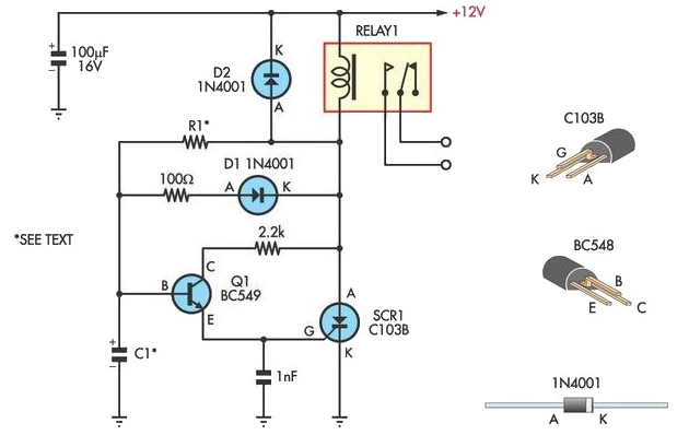
Handy Time Delay With Relay Output
This circuit is designed to provide delayed relay switching action at power on. The delay is a function of the time constant produced by the combination of components.
The circuit operates by utilizing a timing element, typically a resistor-capacitor (RC) network,...
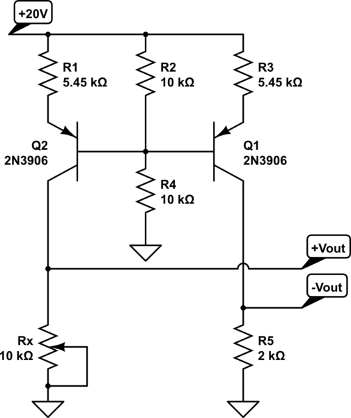
How do you make a shift/scale circuit using a transistor resistors and a voltage source
A functional circuit utilizing an operational amplifier (op-amp); however, the instructor indicated that op-amps can be challenging to work with and provided transistors as an alternative.
Operational amplifiers (op-amps) are versatile components commonly used in various electronic circuits for amplification,...
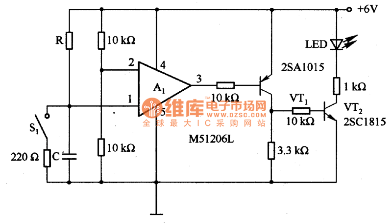
The time delay circuit diagram composed of transistor
The circuit is designed to set a delay time based on the voltage Us and the resistor R. In this configuration, S1 acts as the discharge switch for capacitor C. When switch S1 is closed, the stored charge in capacitor...