


transistors Having difficulties using a darlington (BD681) to drive a 12V fan from an Arduino
#darlington
#BD681
#Arduino
#PWM
#12V fan
#motor control
#breadboard
#circuit design
#speed control
#transistor driver

Description: Power a 12V fan using a Darlington transistor to control the speed from an Arduino. When wired as described, nothing happens even though a PWM signal is being sent. It is suggested to edit the question and ensure the current image is readable. Additionally, check the breadboard as many rows along the side may have interruptions halfway, particularly the Arduino's GND connection. Including a picture of the setup is also recommended.
To power a 12V fan using a Darlington transistor for speed control via an Arduino, the following circuit configuration is advised. The Darlington transistor, which consists of two bipolar junction transistors (BJTs) connected together, provides high current gain and is suitable for switching applications.
The circuit should include an NPN Darlington transistor, such as the TIP120, which is capable of handling the required current for the fan. The Arduino will output a PWM signal to control the fan speed. Connect one of the PWM-capable digital pins of the Arduino (for example, pin 9) to the base of the Darlington transistor through a current-limiting resistor (typically 1kΩ). This resistor is essential to protect the Arduino from excess current.
The collector of the Darlington transistor should be connected to the positive terminal of the 12V power supply, while the emitter connects to one terminal of the fan. The other terminal of the fan should be connected to the ground of the power supply. It is crucial to ensure that the ground of the Arduino is also connected to the ground of the 12V power supply to establish a common reference point.
For additional protection, a flyback diode (e.g., 1N4001) should be placed in parallel with the fan terminals to prevent back EMF generated by the inductive load when the fan is switched off. The cathode of the diode connects to the positive terminal of the fan, while the anode connects to the ground side.
In summary, the circuit consists of an Arduino sending a PWM signal to a resistor connected to the base of a Darlington transistor, which in turn controls the fan powered by a 12V supply. Proper connections and component selection are critical to ensure functionality and prevent damage to the components.Power a 12v fan using a darlington so I can control the speed from an Arduino. When I wire up as below nothing happens, even though I`m sending a PWM signal: Please draw a proper circuit. Edit your question and hit Ctrl+M, the current image is unreadable. Check your breadboard, most rows along the side are have one or two interruptio ns half way (Arduino`s GND connection). Possibly add a picture of your setup aswell. jippie Apr 13 `13 at 20:16
To power a 12V fan using a Darlington transistor for speed control via an Arduino, the following circuit configuration is advised. The Darlington transistor, which consists of two bipolar junction transistors (BJTs) connected together, provides high current gain and is suitable for switching applications.
The circuit should include an NPN Darlington transistor, such as the TIP120, which is capable of handling the required current for the fan. The Arduino will output a PWM signal to control the fan speed. Connect one of the PWM-capable digital pins of the Arduino (for example, pin 9) to the base of the Darlington transistor through a current-limiting resistor (typically 1kΩ). This resistor is essential to protect the Arduino from excess current.
The collector of the Darlington transistor should be connected to the positive terminal of the 12V power supply, while the emitter connects to one terminal of the fan. The other terminal of the fan should be connected to the ground of the power supply. It is crucial to ensure that the ground of the Arduino is also connected to the ground of the 12V power supply to establish a common reference point.
For additional protection, a flyback diode (e.g., 1N4001) should be placed in parallel with the fan terminals to prevent back EMF generated by the inductive load when the fan is switched off. The cathode of the diode connects to the positive terminal of the fan, while the anode connects to the ground side.
In summary, the circuit consists of an Arduino sending a PWM signal to a resistor connected to the base of a Darlington transistor, which in turn controls the fan powered by a 12V supply. Proper connections and component selection are critical to ensure functionality and prevent damage to the components.Power a 12v fan using a darlington so I can control the speed from an Arduino. When I wire up as below nothing happens, even though I`m sending a PWM signal: Please draw a proper circuit. Edit your question and hit Ctrl+M, the current image is unreadable. Check your breadboard, most rows along the side are have one or two interruptio ns half way (Arduino`s GND connection). Possibly add a picture of your setup aswell. jippie Apr 13 `13 at 20:16

Control the speed of a DC motor with a potentiometer with an Arduino board
A quick circuit showing how to control the speed of a DC motor with a potentiometer with your Arduino board. Also shows how to use a TIP120 transistor to allow the Arduino control a larger power supply.
This circuit utilizes an...

DOGM128 with Arduino Hardware
The DOGM graphics module should be connected to the Arduino board as illustrated. Pin 12 (MISO) of the Arduino board must remain unused. Furthermore, the DOGM graphics module requires an address line (A0), which can be connected to any output...
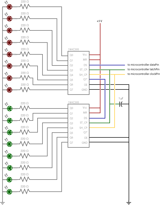
Arduino Shift Out
At some point, it may be necessary to extend the number of pins on an Arduino board using shift registers. This example utilizes the 74HC595, which is described in the datasheet as an "8-bit serial-in, serial or parallel-out shift register...
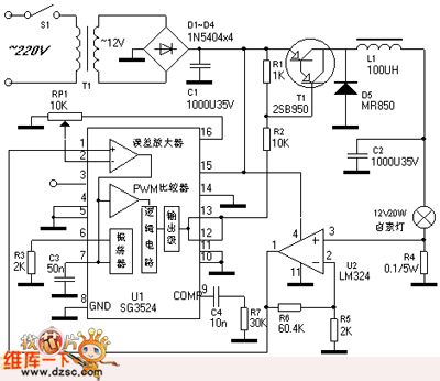
PWM Control Dimming Halogen Lamp
The PWM control dimming circuit for a halogen lamp is illustrated. The halogen lamp operates at a rated voltage of 12V with a nominal power of 20W. This dimmer circuit is capable of adjusting the intensity of the halogen lamp...

A DC motor PWM speed control circuit
Most governors utilize pulse width modulation (PWM) and pulse position modulation (PPM) in their circuits. The 555 timer is commonly used in these applications. The pulse width is typically fixed at 0.5 milliseconds, which is essential for the functioning of...

arduino controllers and sensors
The Arduino microcontroller board can supply a current of 40mA from its output connections, with digital outputs fixed at 5V for "ON" and 0V for "OFF." This current is suitable for LEDs, but devices like motors, solenoids, and high-brightness LEDs...

Speed-Control Switch Circuit
The speed-control switch provides effective control and stability across its entire operating range. This circuit utilizes two SCR devices arranged in a full-wave configuration to manage the DC power supplied to a motor. A center-tapped transformer is employed to provide...

Arduino Motor Knob
Stepper motors, because of their distinct design, can be operated with a high level of precision without the need for feedback mechanisms. The shaft of a stepper motor, equipped with a series of magnets, is governed by a set of...

UC3842AN PWM IC diagram
The UC3842AN is a pulse width modulation (PWM) integrated circuit that is commonly utilized in DVD, VCD, and SVCD players, as well as in computers, display systems, and various household appliances' switching power supply circuits.
The UC3842AN is a versatile...