


1000w exchange regulator automatic voltage regulator circuit diagram
#automatic voltage regulator
#servo motor
#transistor
#1000w
#exchange regulator
#constant output
#3DK9
#power regulation
#circuit diagram

Description: The circuit depicted in the figure includes an automatic voltage regulator (T) that maintains a constant output by utilizing a servo motor. The circuit features transistors VT1 and VT2 (3DK9), with a capacitance range of C (65 ~ 85). Transistor VT3 is specified as 3AX818, with a capacitance range of 60 ~ 80. The circuit incorporates diodes VD2, VD3, and VD6 to VD9 (1N4002); VD4, VD5, and VD10 (1N4148); VD11 (1N4001); and a light-emitting diode VD1 (BT304). A Zener diode VD12 is specified as 2CW119. Capacitors include C1 (1 µF, 400V), C2 and C3 (0.1 µF, 250V), C4 and C5 (220 µF, 25V), C6 (470 µF, 50V), and C7 and C8 (47 µF, 50V). Resistors R1 (10k), R2 and R7 (510), R3 and R6 (2.7k), R4 (470), and R5 (51) are listed, with R1 needing to be rated for more than 3W power, while the others are selected as 1/2 to 1/4W metal film resistors. Potentiometers RP1 and RP2 are rated at 1k. The relays K1 to K3 are specified as JRK-13F, the AC contactor KA as 522, and the servo motor M as ND-D. A voltmeter PV is listed as 85L1-0 to 250V, with switches S1 (KN3-3) and S2 (KN-2W1D), and a fuse FU rated at BGOP µ6-5A.
The circuit serves as an automatic voltage regulation system, designed to maintain a stable output voltage under varying load conditions. The main component, the automatic voltage regulator (T), adjusts the output voltage through feedback from the servo motor, which is mechanically linked to the output stage. This feedback loop ensures that any fluctuations in load do not affect the output voltage, providing a reliable power supply.
Transistors VT1 and VT2 (3DK9) are employed for switching and amplification purposes, ensuring efficient control of the voltage regulation process. The additional transistor VT3 (3AX818) further supports the regulation by enhancing the circuit's response to load changes.
The diode arrangement, including the 1N4002 and 1N4148 types, provides rectification and protection against reverse polarity, ensuring the circuit's longevity and reliability. The light-emitting diode (BT304) serves as an indicator, signaling the operational status of the circuit.
Capacitors are strategically placed throughout the circuit to filter voltage spikes and maintain stability. The selection of capacitors with varying capacitance values allows for effective smoothing of the output voltage, particularly under transient conditions.
The resistors are critical for setting biasing levels and controlling current flow within the circuit. The choice of metal film resistors for most components ensures precision and stability, which is vital for the performance of the voltage regulator.
Potentiometers RP1 and RP2 allow for manual adjustment of the circuit, enabling fine-tuning of the output voltage as required. The relays (JRK-13F) facilitate switching operations, controlling the power delivery to the load based on the feedback from the servo motor.
The AC contactor (522) provides isolation and protection for the circuit, while the voltmeter (85L1-0 to 250V) allows for monitoring the output voltage, ensuring that it remains within specified limits. Switches S1 and S2 enable user interaction with the circuit, providing options for manual control and operation.
Overall, this automatic voltage regulator circuit is designed for efficiency, reliability, and ease of use, making it suitable for various applications where voltage stability is critical. Circuit shown in Figure, T is auto voltage regulator. Its output fixed input end by a servo motor to automatically adjust the output remains constant. Transistor VTl, VT2: 3DK9 C, 65 ~ 85; VT3: 3AX818, 60 ~ 80; diode VD2, VD3, VD6 ~ VD9: 1N4002; VD4, VD5, VD10: 1N4148; VD11: IN4001; light-emitting diodes VD1: BT304; Zener diode VD12: 2CW119; capacitor C1: l F400V; C2, C3: 0.1 F250V; C4, C5: 220 F25V; C6: 470 F50V; C7, C8: 47 F50V; resistance Rl: 10k ; R2, R7: 510 ; R3, R6: 2.7k ; R4: 470 ; R5: 51 ; resistance in addition to the nominal power resistors Rl to select more than 3W power, other are selected 1/2 ~ 1/4W metal film resistors; potentiometer RPl, RP2: 1k ; relay Kl ~ K3: JRK-13F; AC contactor KA: 522; servo motor M: ND-D; voltmeter PV: 85L1-0 ~ 250V; switch S1KN3-3; S2: KN-2W1D; fuse FU: BGOP µ6-5A .
The circuit serves as an automatic voltage regulation system, designed to maintain a stable output voltage under varying load conditions. The main component, the automatic voltage regulator (T), adjusts the output voltage through feedback from the servo motor, which is mechanically linked to the output stage. This feedback loop ensures that any fluctuations in load do not affect the output voltage, providing a reliable power supply.
Transistors VT1 and VT2 (3DK9) are employed for switching and amplification purposes, ensuring efficient control of the voltage regulation process. The additional transistor VT3 (3AX818) further supports the regulation by enhancing the circuit's response to load changes.
The diode arrangement, including the 1N4002 and 1N4148 types, provides rectification and protection against reverse polarity, ensuring the circuit's longevity and reliability. The light-emitting diode (BT304) serves as an indicator, signaling the operational status of the circuit.
Capacitors are strategically placed throughout the circuit to filter voltage spikes and maintain stability. The selection of capacitors with varying capacitance values allows for effective smoothing of the output voltage, particularly under transient conditions.
The resistors are critical for setting biasing levels and controlling current flow within the circuit. The choice of metal film resistors for most components ensures precision and stability, which is vital for the performance of the voltage regulator.
Potentiometers RP1 and RP2 allow for manual adjustment of the circuit, enabling fine-tuning of the output voltage as required. The relays (JRK-13F) facilitate switching operations, controlling the power delivery to the load based on the feedback from the servo motor.
The AC contactor (522) provides isolation and protection for the circuit, while the voltmeter (85L1-0 to 250V) allows for monitoring the output voltage, ensuring that it remains within specified limits. Switches S1 and S2 enable user interaction with the circuit, providing options for manual control and operation.
Overall, this automatic voltage regulator circuit is designed for efficiency, reliability, and ease of use, making it suitable for various applications where voltage stability is critical. Circuit shown in Figure, T is auto voltage regulator. Its output fixed input end by a servo motor to automatically adjust the output remains constant. Transistor VTl, VT2: 3DK9 C, 65 ~ 85; VT3: 3AX818, 60 ~ 80; diode VD2, VD3, VD6 ~ VD9: 1N4002; VD4, VD5, VD10: 1N4148; VD11: IN4001; light-emitting diodes VD1: BT304; Zener diode VD12: 2CW119; capacitor C1: l F400V; C2, C3: 0.1 F250V; C4, C5: 220 F25V; C6: 470 F50V; C7, C8: 47 F50V; resistance Rl: 10k ; R2, R7: 510 ; R3, R6: 2.7k ; R4: 470 ; R5: 51 ; resistance in addition to the nominal power resistors Rl to select more than 3W power, other are selected 1/2 ~ 1/4W metal film resistors; potentiometer RPl, RP2: 1k ; relay Kl ~ K3: JRK-13F; AC contactor KA: 522; servo motor M: ND-D; voltmeter PV: 85L1-0 ~ 250V; switch S1KN3-3; S2: KN-2W1D; fuse FU: BGOP µ6-5A .

circuit to test servo motor (pole rotor) of parabolic antenna
This circuit is designed to test the servo motor of a parabolic antenna. It functions effectively, although a system with a low-noise block feed (LNBF) is generally more suitable. Many users continue to utilize systems that employ an LNB and...

Hands-free-telephone
Transistor Q1 in the headset amplifier circuit amplifies the 30 mV signal intended for the earphones to 0.5 V, which is sufficient to drive stereo earphones. Capacitor C1 blocks any DC current from shorting back into the telephone base. Capacitor...

Dynamic Microphone Preamplifier using C945 transistor
This circuit utilizes three transistors (2SC945, 2C1815, or 2SC828) as the primary components, functioning as a typical low-noise transistor amplifier. It offers a gain of approximately 200 to 300 times and has a frequency response ranging from 50Hz to 100KHz....

Simple Transistor Reflex Receivers
This reflex radio project was inspired by Robert Bazian's design. His reflex radio is the "darndest" thing I have seen and his spectacular results inspired me to come up with my own version! These designs are similar to two-transistor circuits...

Phone In Use Electronics Project
Phone In Use Indicator Electronics Project using 5 resistors, 2 NPN transistors, 4 diodes, and 2 light-emitting diodes.
The Phone In Use Indicator is an electronic project designed to visually indicate when a telephone line is active. This circuit employs a...
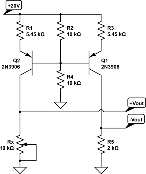
How do you make a shift/scale circuit using a transistor resistors and a voltage source
A functional circuit utilizing an operational amplifier (op-amp); however, the instructor indicated that op-amps can be challenging to work with and provided transistors as an alternative.
Operational amplifiers (op-amps) are versatile components commonly used in various electronic circuits for amplification,...

Transistor regulator circuit can adjustable output voltage
This circuit maintains a constant voltage, with an adjustable output voltage. It serves to reduce the input voltage while keeping the voltage constant. The amplifier model used is the Q1 2N3904 in a common-emitter configuration. This configuration allows the voltage...

OTL transistor radio in a power amplifier circuit
The transistor radio features a common output transformerless (OTL) power amplifier circuit. The VT5 component serves as the bias resistor for the driver stage. VT6 and VT7 form a complementary symmetry configuration, with VT6 being a germanium NPN transistor and...
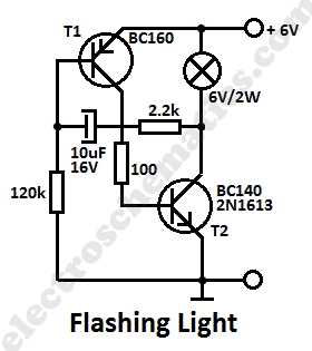
Flashing Light Circuit with Transistors
This simple flashing light circuit operates at 6 volts and 0.5A, exhibiting low current consumption when the light bulb is turned off. The frequency of the flashing is predetermined.
The circuit consists of a power supply, typically a battery or a...