


2.5A/1.25 To 25V Regulated Power Supply

Description: This power supply utilizes an LM317J adjustable regulator along with an MJ2955 pass transistor. Q1 and U2, as well as U1, should be equipped with heatsinks. A suitable heatsink would typically measure 4" x 4" x 1" with fins, extruded type, due to potential dissipation of up to 65 W. Resistors R8 and R9 should be 1% tolerance types or selected from 5% film types using an accurate ohmmeter. Capacitors are primarily disc ceramic, except for those marked with polarity, which are electrolytic. D1 and D2 are 1-A, 100-PIV rectifier diodes. DS1 is a red LED. F1 is a 1.5-A, 3AG fuse in a chassis-mount holder. J1 and J2 are standard five-way binding posts, one red and one black. M1 is a milliammeter with a range of 0-1 mA DC. Q1 is an NPN power transistor MJ2955 (available at Radio Shack) or an equivalent device rated for +70 V, 10 A, and 150 W in a -204 case. R1, R2, and R7 are 5-W wire-wound resistors. For R1 and R7, 17 inches of no. 28 enamel wire can be used, wound in a single layer around a 10-KOhm, 1-W carbon-composition resistor. For R2, 36 inches of no. 30 enamel wire is recommended, wound in a scramble manner around a 10-KOhm, 1-W carbon composition resistor. R4 is a panel-mount, 5-kΩ, 2-W or 5-W potentiometer, which can be carbon or wire wound. R8 and R9 should be selected as per the text. S1 is an SPST toggle switch, while S2 is a DPDT toggle or rotary wafer switch. T1 is a 25.2-V, 2.75-A power transformer. U1 is a 6-A, 200 PIV bridge rectifier with a heatsink. U2 is an LM317T adjustable voltage regulator capable of outputting between +1.25 V to +30 V at 1.5 A. For applications requiring a DC output voltage greater than 40 V, an LM317HVK (TO-204 case) should be used.
The power supply circuit described integrates an adjustable voltage regulator and a pass transistor to provide a stable output voltage across a variable load. The LM317J regulator is a well-known component in power supply design, offering adjustable voltage capabilities. The MJ2955 serves as a high-power pass transistor, enhancing the current handling capacity of the circuit.
The heatsinking requirements are critical for both the LM317J and MJ2955 due to the significant thermal dissipation that can occur under load. The specified heatsink dimensions ensure that the components operate within safe temperature limits, thereby enhancing reliability and performance.
Resistor selection is also paramount, with R8 and R9 being precision resistors to maintain voltage regulation accuracy. The use of high-quality capacitors, particularly in power supply applications, helps in smoothing the output and reducing ripple voltage, which is essential for sensitive electronic applications.
The inclusion of a milliammeter allows for real-time monitoring of the output current, facilitating adjustments and ensuring that the load does not exceed the rated capacity of the power supply. The toggle switches (S1 and S2) allow for easy operation and configuration of the circuit, while the binding posts (J1 and J2) provide a robust connection for output terminals.
Overall, the circuit design emphasizes reliability, precision, and ease of use, making it suitable for a wide range of applications in electronics. The specified components and layout provide a clear roadmap for constructing a high-performance adjustable power supply. This power supply uses an LM317J adjustable regulator and an MJ2955 pass transistor. Ql and U2 as well as Ul should be heatsinked. A suitable heatsink would typically be 4" 4" 1" fins, extruded type, because up to 65 W dissipation can occur. R8 and R9 should be 1% types or selected from 5% film types with an accurate ohmmeter. Capacitors are disc ceramic except for those with polarity marked, which are electrolytic. D1, D2—1-A, 100-PIV rectifier diode. DS1—Red LED. F1 —1,5-A, 3AG fuse in chassis-mount holder. J1, J2—Standard five-way binding post, one red, one black. M1—Milliammeter, 0-1 mA dc. Q1—NPN power transistor MJ2955 (Radio Shack) or equiv device with a + 70-V, 10-A, 150-W rating in a -204 case.
R1, R2, R7—5-W wire-wound resistor. See Notes 3 and 4 for source, or, use 17 inches of no. 28 enam wire, single-layer wound, on a 10-KOhmhm, 1-W carbon-composition resistor for R1 and R7. For R2, use 36 inches of no. 30 enam wire on a 10-KOhmhm, 1-W carbon composition resistor (scramble wound). R-4—Panel-mount, 5-kfi, 2-W or 5-W potentiometer, carbon or wire wound (See Note 8). R8, R9—See text. 51—SPSTtoggle switch. 52—DPDTtoggle or rotary wafer switch. T1—25.2-V, 2.75-A power transformer (see text). U1—6-A, 200 PIV bridge rectifier with heat sink. See text. U2—LM317T +1.25- to 30-V, 1.5-A 7-220 regulator. Use an LM317HVK (T0-204 case) for dc output voltage greater than 40. See text.
The power supply circuit described integrates an adjustable voltage regulator and a pass transistor to provide a stable output voltage across a variable load. The LM317J regulator is a well-known component in power supply design, offering adjustable voltage capabilities. The MJ2955 serves as a high-power pass transistor, enhancing the current handling capacity of the circuit.
The heatsinking requirements are critical for both the LM317J and MJ2955 due to the significant thermal dissipation that can occur under load. The specified heatsink dimensions ensure that the components operate within safe temperature limits, thereby enhancing reliability and performance.
Resistor selection is also paramount, with R8 and R9 being precision resistors to maintain voltage regulation accuracy. The use of high-quality capacitors, particularly in power supply applications, helps in smoothing the output and reducing ripple voltage, which is essential for sensitive electronic applications.
The inclusion of a milliammeter allows for real-time monitoring of the output current, facilitating adjustments and ensuring that the load does not exceed the rated capacity of the power supply. The toggle switches (S1 and S2) allow for easy operation and configuration of the circuit, while the binding posts (J1 and J2) provide a robust connection for output terminals.
Overall, the circuit design emphasizes reliability, precision, and ease of use, making it suitable for a wide range of applications in electronics. The specified components and layout provide a clear roadmap for constructing a high-performance adjustable power supply. This power supply uses an LM317J adjustable regulator and an MJ2955 pass transistor. Ql and U2 as well as Ul should be heatsinked. A suitable heatsink would typically be 4" 4" 1" fins, extruded type, because up to 65 W dissipation can occur. R8 and R9 should be 1% types or selected from 5% film types with an accurate ohmmeter. Capacitors are disc ceramic except for those with polarity marked, which are electrolytic. D1, D2—1-A, 100-PIV rectifier diode. DS1—Red LED. F1 —1,5-A, 3AG fuse in chassis-mount holder. J1, J2—Standard five-way binding post, one red, one black. M1—Milliammeter, 0-1 mA dc. Q1—NPN power transistor MJ2955 (Radio Shack) or equiv device with a + 70-V, 10-A, 150-W rating in a -204 case.
R1, R2, R7—5-W wire-wound resistor. See Notes 3 and 4 for source, or, use 17 inches of no. 28 enam wire, single-layer wound, on a 10-KOhmhm, 1-W carbon-composition resistor for R1 and R7. For R2, use 36 inches of no. 30 enam wire on a 10-KOhmhm, 1-W carbon composition resistor (scramble wound). R-4—Panel-mount, 5-kfi, 2-W or 5-W potentiometer, carbon or wire wound (See Note 8). R8, R9—See text. 51—SPSTtoggle switch. 52—DPDTtoggle or rotary wafer switch. T1—25.2-V, 2.75-A power transformer (see text). U1—6-A, 200 PIV bridge rectifier with heat sink. See text. U2—LM317T +1.25- to 30-V, 1.5-A 7-220 regulator. Use an LM317HVK (T0-204 case) for dc output voltage greater than 40. See text.

Intermittent start and stop cycle control circuit Five of a
The circuit depicted in Figure 3-80 is responsible for controlling a portion of the transistor multivibrator. A multivibrator serves as a robust positive and negative feed-forward amplifier, consisting of two branches that are interconnected through a coupled RC timing circuit,...

Vehicle Detector
A simple single-transistor Colpitts oscillator is depicted in the schematic. When a vehicle passes over the loop, the inductance decreases, resulting in an increase in the oscillator frequency. A microprocessor measures the oscillator frequency and takes appropriate actions based on...

Industrial fuel oil furnace controller circuit diagram 2
The industrial fuel oil furnace controller circuit consists of a power supply circuit, a testing and ignition control circuit, and a control implementation circuit, as illustrated in the accompanying diagram. The power supply circuit includes a step-down capacitor (C6), a...

Example Transistor Circuit with LEDs
A transistor is an electronic component that allows a small current to control a significantly larger current. This characteristic is valuable in various renewable energy projects and other applications. A basic circuit diagram is provided, featuring a 12V LED spotlight...

Single transistor audio mixer
Numerous audio mixer circuits have been published; however, this particular design is among the simplest. This straightforward audio mixer circuit utilizes only a single transistor. The base-emitter junction of the transistor is biased with diodes D1 and D2. The signals...

simple microphone preamplifier
The circuit is a simple one-transistor amplifier with an amplification factor of approximately 30-40 dB, which varies depending on the transistor, temperature, and voltage. The dynamic microphone input is a straightforward one-transistor amplifier circuit with no special features. LED D1...
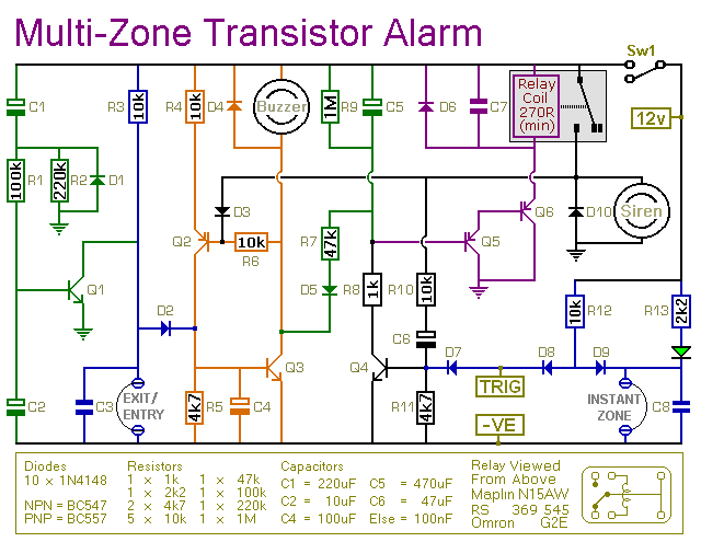
expandable transistor based burglar alarm
This transistor-based alarm system incorporates automatic exit and entry delays, along with a timed bell cut-off and system reset functionality. In addition to the exit/entry zone, the fundamental alarm board includes one instant zone, which is sufficient for many applications....

Basic reference transistor bias circuit - Mixed Negative feedback
Basic reference transistor bias circuit - Mixed Negative feedback
The basic reference transistor bias circuit utilizing mixed negative feedback is a fundamental electronic configuration designed to stabilize the operating point of a transistor. This circuit typically employs a combination of resistive...

Transistor Sensor Temperature Measurer
Using the fact that the VRE of a transistor shifts 59.16 mV per decade of current at 25°C. This constant is 0.33%/°C. This V5E-vs.-current relationship holds true regardless of the FBe absolute value. IC, an LT1043, acts as an oscillator...