


6 Volt regulator circuit using 7806-Voltage regulator IC

Description: A simple 6-volt DC regulator circuit with a diagram and schematic using the 7806 IC, a positive voltage regulator. It serves as an elementary 6-volt, 1-ampere power supply circuit.
The 7806 voltage regulator is a widely used integrated circuit that provides a stable output voltage of 6 volts with a maximum output current of 1 ampere. This circuit is particularly useful for powering low-voltage electronic devices, ensuring consistent performance regardless of variations in input voltage or load conditions.
The basic configuration of the 7806 regulator circuit includes the following components: the 7806 IC, input and output capacitors, and a heat sink if necessary. The input capacitor, typically a 0.33 µF ceramic capacitor, is connected between the input pin of the 7806 and ground to filter out high-frequency noise from the input voltage source. The output capacitor, usually a 0.1 µF ceramic capacitor, is connected between the output pin and ground to improve transient response and stability of the output voltage.
The input voltage supplied to the 7806 must be higher than 6 volts, typically in the range of 7 to 35 volts, to ensure proper regulation. The maximum input-output voltage differential must not exceed the specified limits of the IC to prevent damage. It is also recommended to include a heat sink on the 7806 if the load current approaches the maximum limit, as this will help dissipate heat generated during operation.
The circuit schematic consists of the 7806 IC with its three pins: input (VIN), output (VOUT), and ground (GND). The input voltage is connected to the VIN pin, while the output voltage can be taken from the VOUT pin. The GND pin is connected to the common ground of the circuit. The input and output capacitors are placed close to the IC pins to minimize lead inductance and enhance stability.
Overall, this simple 6-volt DC regulator circuit is an effective solution for providing a reliable power supply for various electronic applications, ensuring that devices receive the necessary voltage for optimal operation.A simple 6 volt dc regulator circuit with diagram and schematic using 7806 Ic, a positive voltage regulator.Its an elementary 6 volt,1 ampere power supply circuit..
The 7806 voltage regulator is a widely used integrated circuit that provides a stable output voltage of 6 volts with a maximum output current of 1 ampere. This circuit is particularly useful for powering low-voltage electronic devices, ensuring consistent performance regardless of variations in input voltage or load conditions.
The basic configuration of the 7806 regulator circuit includes the following components: the 7806 IC, input and output capacitors, and a heat sink if necessary. The input capacitor, typically a 0.33 µF ceramic capacitor, is connected between the input pin of the 7806 and ground to filter out high-frequency noise from the input voltage source. The output capacitor, usually a 0.1 µF ceramic capacitor, is connected between the output pin and ground to improve transient response and stability of the output voltage.
The input voltage supplied to the 7806 must be higher than 6 volts, typically in the range of 7 to 35 volts, to ensure proper regulation. The maximum input-output voltage differential must not exceed the specified limits of the IC to prevent damage. It is also recommended to include a heat sink on the 7806 if the load current approaches the maximum limit, as this will help dissipate heat generated during operation.
The circuit schematic consists of the 7806 IC with its three pins: input (VIN), output (VOUT), and ground (GND). The input voltage is connected to the VIN pin, while the output voltage can be taken from the VOUT pin. The GND pin is connected to the common ground of the circuit. The input and output capacitors are placed close to the IC pins to minimize lead inductance and enhance stability.
Overall, this simple 6-volt DC regulator circuit is an effective solution for providing a reliable power supply for various electronic applications, ensuring that devices receive the necessary voltage for optimal operation.A simple 6 volt dc regulator circuit with diagram and schematic using 7806 Ic, a positive voltage regulator.Its an elementary 6 volt,1 ampere power supply circuit..

Temperature compensation of the symmetrical power supply 7812 F007C
The circuit is a temperature-compensated power supply that generates a negative voltage to track positive voltage changes in a symmetrical voltage integrated power supply. It features a three-terminal regulator connected with two identical transistors, leveraging the temperature characteristics of the...

Regulator Combination Circuits
There are a number of ways to obtain the low voltages required to run small projects from the wall power outlet. The simplest way is to buy a factory-built molded supply which is designed to plug directly into the wall...

Positive-regulator-with-pnp-boost
The IC8211 serves as the voltage reference and regulator amplifier, with Q1 functioning as the series pass transistor. Resistor R1 defines the output current of the IC8211, while capacitors C1 and C2 ensure loop stability and help suppress the feedthrough...
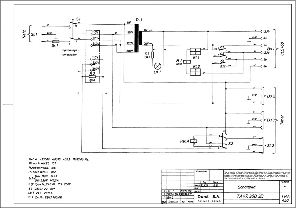
Durst power supplies EST 301 and EST 450
The regulator board of the ES301 has been inspected, revealing that the PCB contacts of the current sensing resistors R42 and R43 are severely burned. There is a nearby group of resistors that also need to be replaced, but their...

250 Watt PC power Supply
Up to 10 A continuous output current, or operation with 50 % ESD and 18 A peak current are possible without a fan if sufficient natural air flow is present and the ambient temperature does not exceed 30 °C. A...

Switching Regulator Circuit
This example presents a switch DC regulated power supply circuit designed for buck-mode +5V applications. It consists of a power supply circuit, an impulsator, a voltage sampling or pulse width modulation circuit, and a buffering driver circuit, as illustrated in...

Changhong DVB-2000 digital satellite receiver switching power supply circuit
The Changhong DVB-2000 digital satellite receiver features a switching power supply circuit. This circuit primarily comprises a power input section, an oscillation switching circuit, and a DC output section. The power input circuit receives 22V AC from a step-down transformer,...

SciTech PS-3R Power Supply Circuit
The following circuit illustrates the SciTech PS-3R Power Supply Circuit. Features include 13.8V DC output, 5 Amps surge capability, and a constant output of 3 Amps. Components include a transistor and others.
The SciTech PS-3R Power Supply Circuit is designed to...
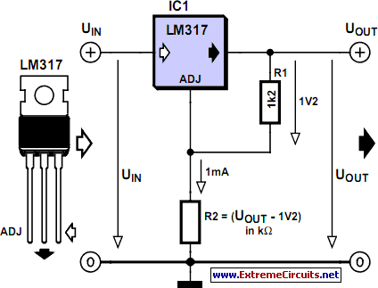
Voltage Regulator Calculation
Before designing an adjustable voltage regulator into a circuit or performing a redesign, it is necessary to calculate the values for two resistors. While this process is straightforward, sourcing the appropriate resistors may present challenges. Fortunately, a method exists to...