


Adjustable Current Regulator Circuit Using LM117
#LM117
#adjustable regulator
#current regulator
#voltage regulation
#negative supply
#reference voltage
#power supply
#circuit schematic

Description: This circuit illustrates an adjustable regulator configuration that incorporates a voltage regulator. In this design, the LM117 regulator is utilized instead of the LM113 diode for reference. Both regulators necessitate a negative supply to function correctly with respect to ground. A circuit schematic accompanies this description.
The adjustable regulator circuit featuring the LM117 is designed to provide a stable output voltage that can be varied according to the requirements of the application. The LM117 is a popular choice for voltage regulation due to its ability to deliver a precise output voltage while accommodating a wide range of input voltages.
In this circuit, the LM117 operates in conjunction with a negative supply, which is essential for its proper functioning. The negative supply allows the circuit to maintain a reference point below ground, ensuring that the output voltage can be adjusted effectively. The adjustment is typically achieved through the use of external resistors, which set the desired output voltage level.
The LM117 is configured with two external resistors, R1 and R2, which form a voltage divider network. The output voltage (Vout) can be calculated using the formula:
Vout = Vref * (1 + R2/R1) + Iadj * R2
where Vref is the reference voltage provided by the LM117 (approximately 1.25V), and Iadj is the adjustment pin current, typically negligible in most applications.
The circuit also includes bypass capacitors to stabilize the input and output voltages. A capacitor placed at the input helps filter any high-frequency noise from the supply voltage, while a capacitor at the output improves transient response and stability.
When designing this circuit, it is crucial to ensure that the power ratings of the resistors and capacitors are suitable for the expected load conditions. Additionally, thermal considerations must be taken into account, as the LM117 may require a heat sink for higher output currents to prevent overheating.
Overall, this adjustable regulator circuit with the LM117 provides a versatile solution for applications requiring variable voltage supply while maintaining high efficiency and stability.This circuit shows the adjustable regulator circuit is conjunction with a voltage regulator, but on this circuit using the LM117 regulator of alternative flows in addition to providing a reference, not a diode LM113. Both regulators currently require a negative supply to operate on the ground. Here is a circuit schematic:
The adjustable regulator circuit featuring the LM117 is designed to provide a stable output voltage that can be varied according to the requirements of the application. The LM117 is a popular choice for voltage regulation due to its ability to deliver a precise output voltage while accommodating a wide range of input voltages.
In this circuit, the LM117 operates in conjunction with a negative supply, which is essential for its proper functioning. The negative supply allows the circuit to maintain a reference point below ground, ensuring that the output voltage can be adjusted effectively. The adjustment is typically achieved through the use of external resistors, which set the desired output voltage level.
The LM117 is configured with two external resistors, R1 and R2, which form a voltage divider network. The output voltage (Vout) can be calculated using the formula:
Vout = Vref * (1 + R2/R1) + Iadj * R2
where Vref is the reference voltage provided by the LM117 (approximately 1.25V), and Iadj is the adjustment pin current, typically negligible in most applications.
The circuit also includes bypass capacitors to stabilize the input and output voltages. A capacitor placed at the input helps filter any high-frequency noise from the supply voltage, while a capacitor at the output improves transient response and stability.
When designing this circuit, it is crucial to ensure that the power ratings of the resistors and capacitors are suitable for the expected load conditions. Additionally, thermal considerations must be taken into account, as the LM117 may require a heat sink for higher output currents to prevent overheating.
Overall, this adjustable regulator circuit with the LM117 provides a versatile solution for applications requiring variable voltage supply while maintaining high efficiency and stability.This circuit shows the adjustable regulator circuit is conjunction with a voltage regulator, but on this circuit using the LM117 regulator of alternative flows in addition to providing a reference, not a diode LM113. Both regulators currently require a negative supply to operate on the ground. Here is a circuit schematic:

A 12 Volt Switching Power Supply
This circuit is designed for individuals needing to boost or drop a voltage. The output operates at high frequency but can be rectified and filtered to provide a DC output. When rectifying high frequencies, it is essential to utilize high-speed...

Self-control digital inverter power supply circuit diagram:1.2V rising to 9V
The circuit does not require a separate power switch or transformation to control the switches on the table. It offers advantages such as low power consumption, stability, reliability, and no impact on instrument accuracy. The transformer T in the circuit...

Current Regulators For LEDs
The following are current regulator circuits that can be used to drive light emitting diodes. As always, take time to do some testing before attempting to use these circuits in actual applications.
Current regulator circuits are essential for controlling the current...
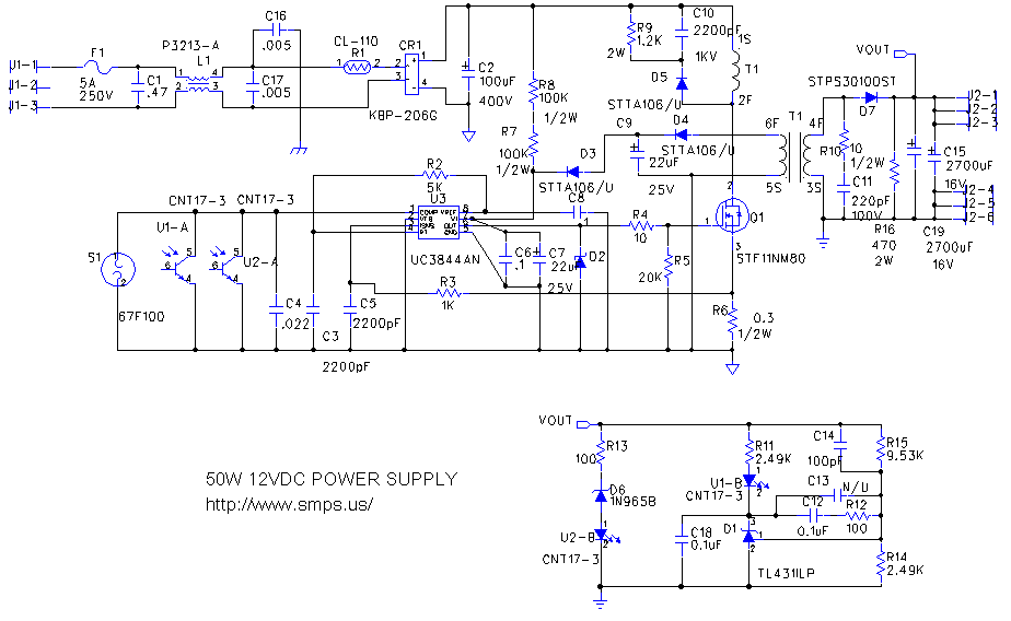
switching power supply 2
This circuit is designed to double nearly any DC input voltage while handling a substantial amount of current. For instance, it can work with input voltages ranging from 12 to 24V. With minor modifications, it can also provide any desired...

Switching Regulator Circuit
This example presents a switch DC regulated power supply circuit designed for buck-mode +5V applications. It consists of a power supply circuit, an impulsator, a voltage sampling or pulse width modulation circuit, and a buffering driver circuit, as illustrated in...

variable voltage and current power supply
An alternative method for utilizing operational amplifiers (op-amps) to regulate a power supply is illustrated below. The power transformer necessitates an additional winding to provide the op-amps with a bipolar voltage of +/- 8 volts. This negative voltage is also...

3-30V 3A Adjustable Regulated DC Power Supply
This power supply is designed as either an auxiliary or a permanent power source for various circuits that require a stabilized DC voltage ranging from 3 to 30V, with a maximum current consumption of 3A. Additionally, this power supply unit...

Power Supply Monitor /Memory Protector
This circuit detects low-voltage supply conditions, down to 0.6 V. Diode D1 sets the trip point of the circuit. The circuit is useful for protecting memory circuits from accidental writes during low-voltage power supply conditions, which can cause other circuits...
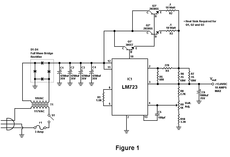
Build A 10 Amp 13.8 Volt Power Supply
Sometimes amateurs like to home-brew their power supplies instead of purchasing one off the shelf at any of the major ham radio retail dealers. The advantage to rolling your own power supply is that it teaches us how they work...