


High Input Voltage regulator using LM340
#LM340
#voltage regulator
#5V
#high voltage
#power supply
#circuit protection
#electronics
#DC voltage
#voltage stabilization

Description: This circuit is a high input voltage regulator that generates a voltage of 5V. In this circuit, the input voltage for the LM340 must remain within the limits specified in the datasheet. Operating the device above the absolute maximum input voltage rating can lead to two potential failure modes. If the output is shorted to ground, or even if the output is not grounded, the transistor Q1 may fail due to being operated with a collector-emitter voltage of approximately 4.0V below the input voltage. If the power supply operates at a higher voltage than the specified maximum, a simple method to protect the regulator is to connect a zener diode in series with the input to level shift the input voltage. A schematic drawing is provided.
The high input voltage regulator circuit utilizes an LM340 voltage regulator to maintain a stable output voltage of 5V. The LM340 is designed to operate within specific input voltage limits as detailed in its datasheet. Exceeding these limits can lead to catastrophic failure modes, particularly affecting the transistor Q1, which is crucial for regulating the output voltage.
In the event of an output short circuit, the collector-emitter voltage of Q1 can reach levels that exceed its maximum ratings, leading to thermal runaway and eventual failure. Additionally, if the output is not grounded, the same issue can occur due to excessive voltage stress on the transistor. To mitigate these risks, the circuit incorporates a zener diode, which is connected in series with the input voltage. This configuration effectively clamps the input voltage to a safe level, ensuring that the LM340 operates within its specified limits.
The zener diode serves as a protective element, allowing the circuit to tolerate higher input voltages without compromising the integrity of the regulator. By selecting an appropriate zener voltage, the input can be level-shifted to maintain the necessary voltage for proper operation of the LM340.
The schematic of the circuit would typically include the LM340, the zener diode, and associated passive components such as resistors and capacitors to ensure stability and performance. Capacitors may be included at the output to filter any ripple and maintain a steady voltage output, while additional components may be used to enhance transient response and overall efficiency. Proper layout and thermal management are also critical in the design to prevent overheating and ensure reliable operation over a range of environmental conditions.This circuit is the High Input Voltage regulators, which generate voltage 5V. In these circuit LM340 input voltage must remain within the limits specified in the data sheet. If the device is operated above the absolute maximum input voltage rating, two failure modes can occur. With the output shorted to ground, or, even with the output is not grou nded, the transistor Q1 may fail because it is operated with the collector-emitter voltage of about 4. 0V below the input. If the supply is available only running at a higher voltage than the specified maximum, one of the simplest ways to protect the regulator is to connect the zener diode in series with input from the device to level shift the input voltage.
Here is a schematic drawing:
The high input voltage regulator circuit utilizes an LM340 voltage regulator to maintain a stable output voltage of 5V. The LM340 is designed to operate within specific input voltage limits as detailed in its datasheet. Exceeding these limits can lead to catastrophic failure modes, particularly affecting the transistor Q1, which is crucial for regulating the output voltage.
In the event of an output short circuit, the collector-emitter voltage of Q1 can reach levels that exceed its maximum ratings, leading to thermal runaway and eventual failure. Additionally, if the output is not grounded, the same issue can occur due to excessive voltage stress on the transistor. To mitigate these risks, the circuit incorporates a zener diode, which is connected in series with the input voltage. This configuration effectively clamps the input voltage to a safe level, ensuring that the LM340 operates within its specified limits.
The zener diode serves as a protective element, allowing the circuit to tolerate higher input voltages without compromising the integrity of the regulator. By selecting an appropriate zener voltage, the input can be level-shifted to maintain the necessary voltage for proper operation of the LM340.
The schematic of the circuit would typically include the LM340, the zener diode, and associated passive components such as resistors and capacitors to ensure stability and performance. Capacitors may be included at the output to filter any ripple and maintain a steady voltage output, while additional components may be used to enhance transient response and overall efficiency. Proper layout and thermal management are also critical in the design to prevent overheating and ensure reliable operation over a range of environmental conditions.This circuit is the High Input Voltage regulators, which generate voltage 5V. In these circuit LM340 input voltage must remain within the limits specified in the data sheet. If the device is operated above the absolute maximum input voltage rating, two failure modes can occur. With the output shorted to ground, or, even with the output is not grou nded, the transistor Q1 may fail because it is operated with the collector-emitter voltage of about 4. 0V below the input. If the supply is available only running at a higher voltage than the specified maximum, one of the simplest ways to protect the regulator is to connect the zener diode in series with input from the device to level shift the input voltage.
Here is a schematic drawing:

30KV Power supply / Generator
Easy to build, this high voltage generator is capable of generating up to 50KV but the breakdown voltage of the coil limits the voltage to a value somewhat lower. T2 is the ignition coil of a car and also the...

AMPLIFIER WITH FORCED EQUILIBRIUM ADAPTOR
Each power supply, whether linear or switching, operates in at least two modes: constant voltage (CV) and constant current (CC). The power supply can function in either mode, with the other serving as a protective mode for both the load...

High Voltage Substations Overview
A distribution substation is defined by the apparent power of the transformer and its configuration, which can be aerial, terrestrial, or underground.
A distribution substation plays a critical role in the electrical power distribution network. It serves as a point where...
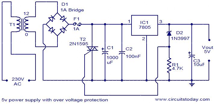
5V power supply with overvoltage protection
For circuits using TTL ICs, the supply voltage is a significant concern, as even a slight increase from the rated 5V can damage the IC. Relying solely on fuses is insufficient since a fuse may take several milliseconds to blow,...

Three-rail-power-supply
This circuit generates three supply voltages using a minimal number of components. Diodes D2 and D3 perform full-wave rectification, alternately charging capacitor C2 during both halves of the AC cycle. Meanwhile, diode D1 in conjunction with capacitor C1, and diode...

2 watt switching power supply
This compact switching power supply utilizes a Schmitt trigger oscillator to control a switching transistor, which provides current to a small inductor. When the transistor is activated, energy accumulates in the inductor, and this energy is subsequently released into the...

Batteries charger & PSU - ideal for digital camerass
This circuit was designed for digital cameras, which are known to have significant power consumption. For instance, the Minolta E223 camera requires approximately 800 mA. In practice, this demand can be met using a mains power supply or high-capacity NiMH...

Stable Filament Power Supply Circuit
The circuit diagram illustrates a voltage regulator designed from discrete components to meet specific voltage requirements. It provides two sets of component values for output voltages of 6.3 V (upper) and 12.6 V (lower). The components used include BC547 and...

High Voltage Electrolytic Capacitor Reformer
High voltage electrolytic capacitors in valve equipment can deteriorate if the equipment is unused for an extended period. This deterioration manifests as reduced capacitance and significantly increased leakage current. In some instances, the capacitor may become nearly short-circuited. Using equipment...