


high input voltage regulators using lm340
#LM340
#voltage regulation
#high voltage
#15V output
#transistor protection
#power supply
#voltage stability
#circuit protection
#electronic components
#DC voltage

Description: This circuit can generate a voltage of 15V. In this circuit, the LM340 input voltage must remain within the limits specified in the data sheet. If the device is operated above the absolute maximum input voltage rating, two failure modes can occur. With the output shorted to ground, or even if the output is not grounded, the transistor Q1 may fail because it is operated with the collector-emitter voltage of about 4.0V below the input. If the supply is only available at a higher voltage than the specified maximum, one of the simplest ways to protect the regulator is to connect a zener diode in series with the input from the device to level shift the input voltage.
This circuit employs the LM340 voltage regulator to provide a stable 15V output. The LM340 is designed to operate within a specified input voltage range, as outlined in its data sheet. Exceeding the absolute maximum input voltage can lead to potential failure modes, primarily affecting the transistor Q1. When the output is shorted to ground, or if the output remains ungrounded, the transistor may experience excessive voltage across its collector-emitter junction, leading to its failure. The critical threshold for safe operation is approximately 4.0V below the input voltage.
To mitigate the risk of operating the LM340 outside its safe input voltage range, a zener diode can be implemented in series with the input voltage supply. This configuration effectively limits the input voltage to a safe level, thereby protecting the regulator and ensuring reliable operation. The zener diode should be selected based on the desired clamping voltage, which should be lower than the maximum input voltage rating specified for the LM340.
The schematic for this circuit should include the LM340 voltage regulator, the zener diode connected in series with the input, and the necessary bypass capacitors to stabilize the output voltage. It is also advisable to include a fuse or other protective components to safeguard against overcurrent conditions. The design should ensure that all components are rated appropriately for the expected voltage and current levels to maintain circuit integrity and reliability.This circuit can generate voltage 15V. In these circuit LM340 input voltage must remain within the limits specified in the data sheet. If the device is operated above the absolute maximum input voltage rating, two failure modes can occur. With the output shorted to ground, or, even with the output is not grounded, the transistor Q1 may fail becaus
e it is operated with the collector-emitter voltage of about 4. 0V below the input. If the supply is available only running at a higher voltage than the specified maximum, one of the simplest ways to protect the regulator is to connect the zener diode in series with input from the device to level shift the input voltage. Here is a schematic drawing:
This circuit employs the LM340 voltage regulator to provide a stable 15V output. The LM340 is designed to operate within a specified input voltage range, as outlined in its data sheet. Exceeding the absolute maximum input voltage can lead to potential failure modes, primarily affecting the transistor Q1. When the output is shorted to ground, or if the output remains ungrounded, the transistor may experience excessive voltage across its collector-emitter junction, leading to its failure. The critical threshold for safe operation is approximately 4.0V below the input voltage.
To mitigate the risk of operating the LM340 outside its safe input voltage range, a zener diode can be implemented in series with the input voltage supply. This configuration effectively limits the input voltage to a safe level, thereby protecting the regulator and ensuring reliable operation. The zener diode should be selected based on the desired clamping voltage, which should be lower than the maximum input voltage rating specified for the LM340.
The schematic for this circuit should include the LM340 voltage regulator, the zener diode connected in series with the input, and the necessary bypass capacitors to stabilize the output voltage. It is also advisable to include a fuse or other protective components to safeguard against overcurrent conditions. The design should ensure that all components are rated appropriately for the expected voltage and current levels to maintain circuit integrity and reliability.This circuit can generate voltage 15V. In these circuit LM340 input voltage must remain within the limits specified in the data sheet. If the device is operated above the absolute maximum input voltage rating, two failure modes can occur. With the output shorted to ground, or, even with the output is not grounded, the transistor Q1 may fail becaus
e it is operated with the collector-emitter voltage of about 4. 0V below the input. If the supply is available only running at a higher voltage than the specified maximum, one of the simplest ways to protect the regulator is to connect the zener diode in series with input from the device to level shift the input voltage. Here is a schematic drawing:
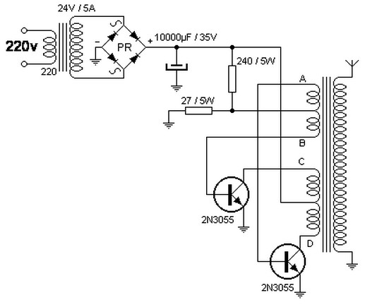
converter 220v ac to 40kv ac
The step-up transformer described can be repurposed as a flyback transformer from an unused television. It is advisable to utilize a basic model without a voltage tripler or high-voltage diode. This type of transformer is capable of generating voltages up...

Low Cost High Voltage Power Supply
This high voltage, low current power supply has been designed for various experiments in systems and synthetic biology. The schematic and board layout are provided below. The circuit can output up to +1,866 VDC at under 1 mA and can...

Various Schematics and Diagrams
Energy storage capacitors in even the smallest disposable camera flash powered by a 1.5 V AA battery can be hazardous under certain conditions. Line-powered devices, regardless of size, may present additional risks due to high power at high voltage and...

Jacobs Ladder
Construct this engaging Jacob's Ladder to observe electric arcs ascending the ladder and dissipating into the atmosphere. It operates using a sophisticated 12,000-volt power supply. The author, Robert Iannini, notes that electric arcs have long captivated and intimidated people, manifesting...

Changhong DVB-2000 digital satellite receiver switching power supply circuit
The Changhong DVB-2000 digital satellite receiver features a switching power supply circuit. This circuit primarily comprises a power input section, an oscillation switching circuit, and a DC output section. The power input circuit receives 22V AC from a step-down transformer,...

MAX668 16V 4.4A switching power supply circuit design electronic project
A simple 16-volt switching power supply circuit can be constructed using the provided diagram, which is based on the MAX668 constant-frequency, pulse-width modulating (PWM), current-mode DC-DC controller. This integrated circuit is designed for a wide range of DC-DC conversion applications...

Panasonic M12H switching power supply circuit diagram
The Panasonic M12H switching power supply circuit is utilized in Panasonic models such as TC-230H, TC-2030DHN, TC-830D, and TC-840D. The circuit operates with an oscillation frequency that generates approximately 300V DC voltage at C836. The T801 transformer is involved in...

Remote tracking circuit schematics
The circuit consists of two main components: (1) a power supply circuit featuring a transformer (T) that steps down AC 220V to 33V, followed by a full-wave rectifier, a filter, and a three-terminal regulator that outputs +24V. This circuit also...

High operating voltage regulator circuit diagram
The voltage equation Ue = Ut + Ur + Ua indicates that the transistor voltage Ut will determine the maximum output voltage Ua. Additionally, Ur must be 2V. The voltage regulator's voltage value depends on the selection of Uz. In...