


HV REGULATOR WITH FOLDBACK CURRENT LIMIT
#HV regulator
#foldback current limit
#pass transistors
#power regulation
#current sensing
#voltage threshold
#power shutdown
#high voltage
#R8 sensing
#D4 threshold

Description: The output current is sensed across R8 and delivered to the current-limit amplifier through R7, where the foldback potential is developed by R6, with a threshold determined by D4. The specified values limit the peak power to below 20 W and shut off the pass transistors when the voltage across them exceeds 310 V. When the unregulated input voltage exceeds this value, the start-up is initiated solely by the current through R5. Q4 is included to provide some control over the current before A2 has time to react. The circuit remains stable with an output capacitor greater than approximately 2 F. Spurious oscillations in current limit are suppressed by C2 and R4, while an unusual latch-mode oscillation emerging from current limit is eliminated using C1 and R1.
The circuit employs a current sensing mechanism through resistor R8, which allows for the monitoring of output current levels. This sensed current is then fed into a current-limit amplifier via resistor R7. The amplifier operates based on a foldback potential established by resistor R6, with the threshold for this operation being set by diode D4. The design ensures that the peak power output is limited to below 20 W, providing a safeguard against excessive power levels. If the voltage across the pass transistors exceeds 310 V, a protective mechanism is triggered to shut them off, thereby preventing damage to the circuit.
In scenarios where the unregulated input voltage surpasses 310 V, the circuit initiates a start-up sequence driven solely by the current flowing through resistor R5. The inclusion of transistor Q4 is critical, as it offers preliminary control over the current flow before the operational amplifier A2 can respond effectively. This feature enhances the responsiveness of the circuit during the start-up phase.
Stability of the circuit is maintained with the use of an output capacitor that exceeds approximately 2 F. This large capacitance helps to smoothen the output and mitigate any potential fluctuations. Additionally, to combat spurious oscillations that may arise during current limiting, capacitors C2 and resistor R4 are strategically placed to filter these disturbances. Furthermore, to address and eliminate any latch-mode oscillations that may occur as a result of current limiting, capacitors C1 and resistor R1 are employed. This comprehensive design facilitates reliable performance while safeguarding against various operational anomalies.The output current issensed across R8, This is delivered to the current-limit arrtplifier through R7, across which the foldback potential is developed by R6 with a threshold determined by D4. The values given limit the peak power below 20 W and shut off the pass transistors when the voltage across them exceeds 310 V.
With unregulated input voltage s above this value, start-up is initiated solely by the current through R5. Q4 is added to provide some control on current before A2 has time to react. The circuit is stable with an output capacitor greater than about 2 F. Spurious oscillations in current limit are suppressed by C2 and R4, while a strange, latch-mode oscillation coming out of current limit is killed with C1 and R1.
The circuit employs a current sensing mechanism through resistor R8, which allows for the monitoring of output current levels. This sensed current is then fed into a current-limit amplifier via resistor R7. The amplifier operates based on a foldback potential established by resistor R6, with the threshold for this operation being set by diode D4. The design ensures that the peak power output is limited to below 20 W, providing a safeguard against excessive power levels. If the voltage across the pass transistors exceeds 310 V, a protective mechanism is triggered to shut them off, thereby preventing damage to the circuit.
In scenarios where the unregulated input voltage surpasses 310 V, the circuit initiates a start-up sequence driven solely by the current flowing through resistor R5. The inclusion of transistor Q4 is critical, as it offers preliminary control over the current flow before the operational amplifier A2 can respond effectively. This feature enhances the responsiveness of the circuit during the start-up phase.
Stability of the circuit is maintained with the use of an output capacitor that exceeds approximately 2 F. This large capacitance helps to smoothen the output and mitigate any potential fluctuations. Additionally, to combat spurious oscillations that may arise during current limiting, capacitors C2 and resistor R4 are strategically placed to filter these disturbances. Furthermore, to address and eliminate any latch-mode oscillations that may occur as a result of current limiting, capacitors C1 and resistor R1 are employed. This comprehensive design facilitates reliable performance while safeguarding against various operational anomalies.The output current issensed across R8, This is delivered to the current-limit arrtplifier through R7, across which the foldback potential is developed by R6 with a threshold determined by D4. The values given limit the peak power below 20 W and shut off the pass transistors when the voltage across them exceeds 310 V.
With unregulated input voltage s above this value, start-up is initiated solely by the current through R5. Q4 is added to provide some control on current before A2 has time to react. The circuit is stable with an output capacitor greater than about 2 F. Spurious oscillations in current limit are suppressed by C2 and R4, while a strange, latch-mode oscillation coming out of current limit is killed with C1 and R1.

Tesla Coil
This webpage is designed to provide assistance and information for individuals interested in constructing a Tesla coil. It is recommended to utilize the additional resources available on this page. The electrical line voltage standard in the United States is 120V...

High voltage supply
A 6 V battery can provide 100-150 Vdc center-tapped at a high internal impedance (not dangerous though it can inflict an unpleasant jolt). A 6.3 V transformer is connected in reverse with a transistor used in a Hartley oscillator configuration....

high voltage circuits
The diagram illustrates a series connection of cell diode capacitors, each rated for an increasing voltage of 300 V. This configuration generates a high DC voltage supply of 40 kV, which can be utilized for various experimental applications. With the...

High Voltage Switching for Energy Recovery
This is a High Voltage switching device for driving coils and which have big impedance when it is switched off. It can be used in Back-EMF energy recovery tests, Newman coils electronic commutator. This device is driven by an opto-coupler...

High Side Current Sensing for Low Side Switching
The AD8205 can be utilized to create a high-side current sensing circuit with a low-side switch. In this configuration, an inductive load (such as a solenoid) and a resistive shunt are incorporated. The resistive shunt is positioned on the high...

High Voltage Power Supply for Valve Preamplifiers
The amplifier feeding the final amplification stage operates with unstabilized voltage. The output stage, utilizing push-pull operation, exhibits significant rejection of the supply voltage. However, the earlier stages do not provide the same level of rejection, resulting in unwanted noise....

Zhichuan Electronic Circuit
The saying goes "dead ringworm surgical, medical dead asthma." This example describes an electronic anti-asthmatic device that produces high-voltage stimulation pulses, which can serve as an adjunct therapy for patients suffering from cough. The circuit consists of a self-excited multivibrator,...

High Voltage Solid State Flyback Driver
Fully illustrated and schematized plans for a high-performance, easy-to-build transistorized high voltage flyback driver.
The high voltage flyback driver circuit is designed to efficiently convert low voltage DC into high voltage pulses suitable for driving flyback transformers. The circuit typically utilizes...
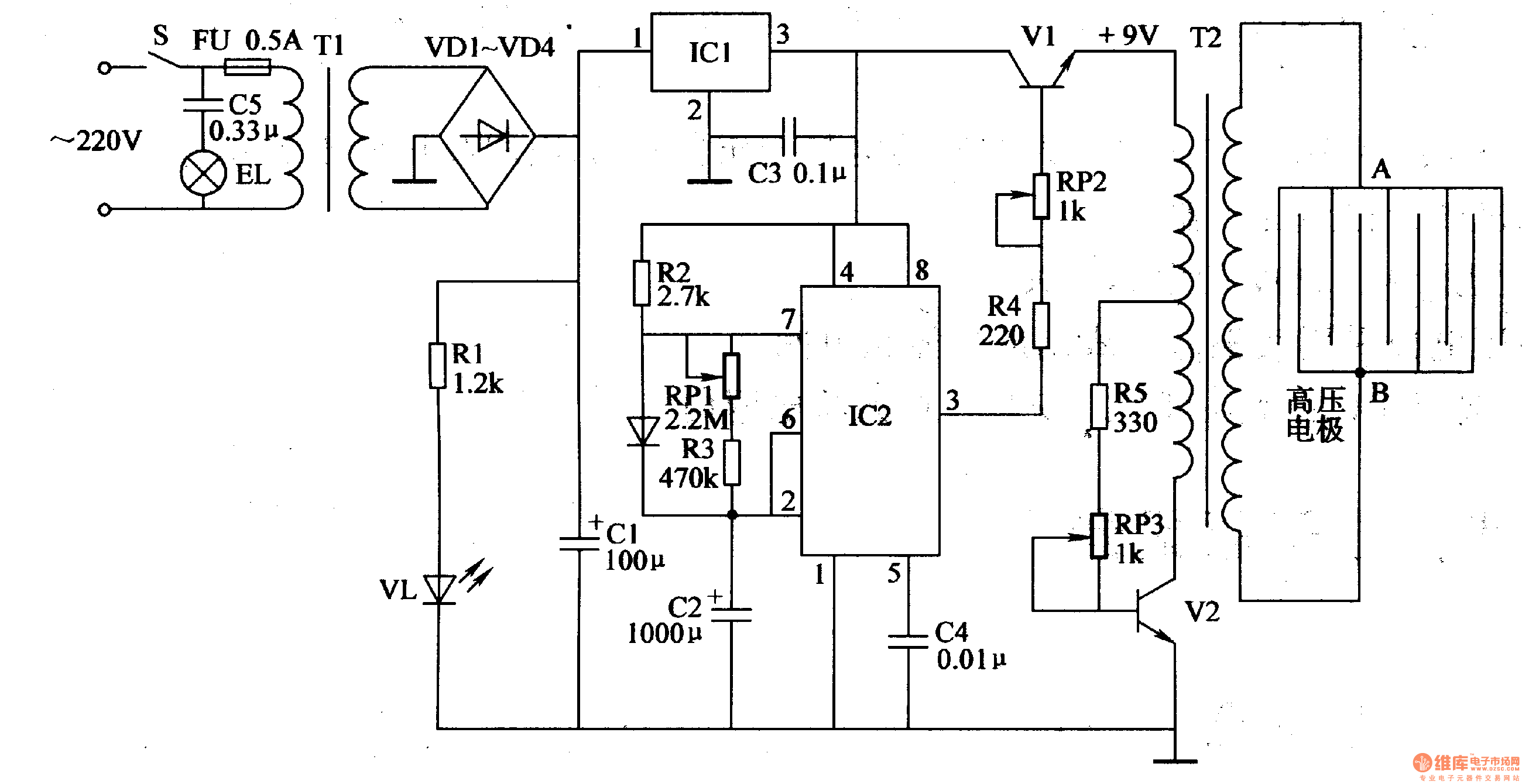
Electronic Pest Killing Lamp
Working Principle: The circuit, as illustrated in figure 4-187, is composed of three main components: the power circuit, the pulse oscillator, and the high voltage generator. The power circuit includes components S, FU, TI, VD1-VD4, C1, C3, IC1, R1, and...