


project DBS
#voltage sag
#9v circuit
#voltage depletion
#pedal power
#voltage control
#power management
#voltage regulation
#electronics

Description: Voltage depletion, often referred to as "sag," is a phenomenon that can be implemented in a circuit, commonly known as a 9V sag circuit. It is advisable to avoid using the term "sag" due to potential confusion with tube amplifier sag, which is a different concept. A common inquiry regarding this topic is whether lowering the voltage can damage a pedal. The straightforward answer is no; a pedal will not be harmed by reduced voltage. If pedals were susceptible to damage from lower voltage, they would also be at risk as batteries begin to deplete. Conversely, increasing the voltage supplied to pedals can cause damage, ranging from burning out limiting diodes to potentially causing smoke and destruction of the circuit. Unlike overclocking a CPU, this situation involves a different set of electrical principles.
A fundamental characteristic of batteries is their series resistance, which increases as the battery discharges. To emulate this behavior of a fading battery, a resistor is placed in series between the battery and the circuit. For adjustable control, a potentiometer is used in lieu of a fixed resistor. Constructing a dying battery simulator using series resistance is straightforward. An alternative method involves using a voltage divider instead of a series resistor. In this configuration, the potentiometer is wired to divide the voltage, and a small resistor is added between the potentiometer and ground to prevent complete voltage reduction and potential overload of the power supply.
The schematic utilizes a 10K potentiometer, although other values such as 100K or 1M can also be employed. The resistor value determines the minimum voltage reduction. A table can be created to suggest various resistor values. The wiring is similar to the series example, where the potentiometer's wiper serves as the output, and one terminal connects to ground.
To visually indicate the current voltage while adjusting the drop control, an analog panel meter rated for 0-10VDC or 0-15VDC can be integrated into the circuit. It is essential to connect the meter after the potentiometer to accurately reflect the voltage drop, rather than before, which would show the full voltage regardless of the potentiometer setting. Although this may seem obvious, it is a common oversight. This method is applicable to both series and voltage divider configurations.
For enhanced functionality, a switch can be added to disconnect the meter from the circuit while keeping the potentiometer active. This may be beneficial in certain circuits where the meter introduces inductance or additional resistance that could alter the circuit's behavior. While there may not be a noticeable difference in sound with the meter connected, the option to isolate it could help maintain the original tonal quality of the effect.
The entire assembly can be neatly enclosed within a standard effects pedal housing. A compact enclosure can be selected, with holes drilled for the potentiometer, meter, and optional switch. Additional holes should be created to accommodate the 9V DC adapter plug. After wiring the components, the device will be ready for use, allowing exploration of voltage variations across various pedals. It is important to note that when using an AC adapter with a voltage sag circuit, the voltage will sag across the power source, meaning that all outputs from a daisy chain power supply will experience this sag effect.Voltage depletion is also called "sag" by some folks. The same general concept I`m covering in this project may be referred to as a 9v sag circuit. I learned to avoid using the word "sag" as many folks confuse it with tube amp sag which is an entirely different matter. Obvious question: Will lowering the voltage damage my pedal . Easy answer: No, it won`t. Think about it ”if a pedal could be damaged by lower voltage, what would happen when your battery started dying The inverse of this project, i. e. a voltage "booster" is not a good thing. You can lower the voltage without hurting anything. You can also raise the voltage into your pedals, but you will hurt things. In the best case scenario, you`ll burn out the limiting diode, worse case you`ll get a ball of smoke, stink, and and empty slot in your pedal board.
It`s not like overclocking your CPU, different concept altogether. A key characteristic of a battery is that it presents a series resistance. As the battery dies, this series resistance increases. So in order to simulate that characteristic of a dying battery, we insert a resistor between the battery and the circuit. And to make it adjustable, we use a potentiometer instead of a fixed resistor. So to build a dying battery simulator using series resistance, it is as simple as this: Another technique is to replace the series resistor with a voltage divider.
In this case we wire the potentiometer differently so that it actually divides the voltage. We also add a small resistor between the potentiometer and ground so that we can`t accidentally turn the voltage sag all the way down and overload the power supply. Here`s the schematic. Note that I`m using a 10K pot, but just about any value pot will work, i. e. 100k, 1Meg, etc. The value of the resistor sets the low end of the voltage reduction. The following table shows some values to try: You`ll see that this is quite similar to the series example, except the potentiometer`s wiper becomes the output and lug 1 goes to ground.
Here`s how you would wire it up: The next step would be to add some type of visual indication as to the current voltage as you play with the drop control. Let`s say you dial in the perfect sound with your drop at about 90% full on (i. e. your drop knob is at about 9 out of 10). Wouldn`t it be nice to be able to actually see the actual voltage An analog panel meter in the 0-10vdc or 0-15vdc works fine in this arrangement.
Notice how the meter taps into the 9v circuit after the potentiometer. If you tapped in before, your meter would always read the full voltage value, regardless of the potentiometer setting. Of course this sounds obvious, but I thought I`d point it out since I`ve made that mistake. This approach works for both the series and the voltage divider configurations. Finally, if you want to get very fancy, you can add a switch that takes the meter out of circuit, but leaves the potentiometer in circuit.
Why Well, I`m not sure, but there may be some circuits where the meter acts as an inductor, or adds additional resistance that make affect the behavior of the overall effect. I have yet to come across a circuit where there is any audible difference with the meter in circuit, but if you want to ensure the pristine original tonality of your effect, add a switch that disconnects one side of the meter.
You can wrap this all up neatly in a typical effects enclosure also. Get a smallish size enclosure, drill a hole for the potentiometer, and the meter and switch if you want to include that. Drill holes on either side for the 9v DC adaptor plug. Wire it up and you`re ready to go voltage spelunking on all your pedals. When you use an AC adaptor with a voltage sagger, be sure to note that the voltage will sag across the power source-this means that if you use a daisy chain adaptor, all the outputs on the daisy chain will be sagged.
For example, if you use a daisy chain power supply like the
A fundamental characteristic of batteries is their series resistance, which increases as the battery discharges. To emulate this behavior of a fading battery, a resistor is placed in series between the battery and the circuit. For adjustable control, a potentiometer is used in lieu of a fixed resistor. Constructing a dying battery simulator using series resistance is straightforward. An alternative method involves using a voltage divider instead of a series resistor. In this configuration, the potentiometer is wired to divide the voltage, and a small resistor is added between the potentiometer and ground to prevent complete voltage reduction and potential overload of the power supply.
The schematic utilizes a 10K potentiometer, although other values such as 100K or 1M can also be employed. The resistor value determines the minimum voltage reduction. A table can be created to suggest various resistor values. The wiring is similar to the series example, where the potentiometer's wiper serves as the output, and one terminal connects to ground.
To visually indicate the current voltage while adjusting the drop control, an analog panel meter rated for 0-10VDC or 0-15VDC can be integrated into the circuit. It is essential to connect the meter after the potentiometer to accurately reflect the voltage drop, rather than before, which would show the full voltage regardless of the potentiometer setting. Although this may seem obvious, it is a common oversight. This method is applicable to both series and voltage divider configurations.
For enhanced functionality, a switch can be added to disconnect the meter from the circuit while keeping the potentiometer active. This may be beneficial in certain circuits where the meter introduces inductance or additional resistance that could alter the circuit's behavior. While there may not be a noticeable difference in sound with the meter connected, the option to isolate it could help maintain the original tonal quality of the effect.
The entire assembly can be neatly enclosed within a standard effects pedal housing. A compact enclosure can be selected, with holes drilled for the potentiometer, meter, and optional switch. Additional holes should be created to accommodate the 9V DC adapter plug. After wiring the components, the device will be ready for use, allowing exploration of voltage variations across various pedals. It is important to note that when using an AC adapter with a voltage sag circuit, the voltage will sag across the power source, meaning that all outputs from a daisy chain power supply will experience this sag effect.Voltage depletion is also called "sag" by some folks. The same general concept I`m covering in this project may be referred to as a 9v sag circuit. I learned to avoid using the word "sag" as many folks confuse it with tube amp sag which is an entirely different matter. Obvious question: Will lowering the voltage damage my pedal . Easy answer: No, it won`t. Think about it ”if a pedal could be damaged by lower voltage, what would happen when your battery started dying The inverse of this project, i. e. a voltage "booster" is not a good thing. You can lower the voltage without hurting anything. You can also raise the voltage into your pedals, but you will hurt things. In the best case scenario, you`ll burn out the limiting diode, worse case you`ll get a ball of smoke, stink, and and empty slot in your pedal board.
It`s not like overclocking your CPU, different concept altogether. A key characteristic of a battery is that it presents a series resistance. As the battery dies, this series resistance increases. So in order to simulate that characteristic of a dying battery, we insert a resistor between the battery and the circuit. And to make it adjustable, we use a potentiometer instead of a fixed resistor. So to build a dying battery simulator using series resistance, it is as simple as this: Another technique is to replace the series resistor with a voltage divider.
In this case we wire the potentiometer differently so that it actually divides the voltage. We also add a small resistor between the potentiometer and ground so that we can`t accidentally turn the voltage sag all the way down and overload the power supply. Here`s the schematic. Note that I`m using a 10K pot, but just about any value pot will work, i. e. 100k, 1Meg, etc. The value of the resistor sets the low end of the voltage reduction. The following table shows some values to try: You`ll see that this is quite similar to the series example, except the potentiometer`s wiper becomes the output and lug 1 goes to ground.
Here`s how you would wire it up: The next step would be to add some type of visual indication as to the current voltage as you play with the drop control. Let`s say you dial in the perfect sound with your drop at about 90% full on (i. e. your drop knob is at about 9 out of 10). Wouldn`t it be nice to be able to actually see the actual voltage An analog panel meter in the 0-10vdc or 0-15vdc works fine in this arrangement.
Notice how the meter taps into the 9v circuit after the potentiometer. If you tapped in before, your meter would always read the full voltage value, regardless of the potentiometer setting. Of course this sounds obvious, but I thought I`d point it out since I`ve made that mistake. This approach works for both the series and the voltage divider configurations. Finally, if you want to get very fancy, you can add a switch that takes the meter out of circuit, but leaves the potentiometer in circuit.
Why Well, I`m not sure, but there may be some circuits where the meter acts as an inductor, or adds additional resistance that make affect the behavior of the overall effect. I have yet to come across a circuit where there is any audible difference with the meter in circuit, but if you want to ensure the pristine original tonality of your effect, add a switch that disconnects one side of the meter.
You can wrap this all up neatly in a typical effects enclosure also. Get a smallish size enclosure, drill a hole for the potentiometer, and the meter and switch if you want to include that. Drill holes on either side for the 9v DC adaptor plug. Wire it up and you`re ready to go voltage spelunking on all your pedals. When you use an AC adaptor with a voltage sagger, be sure to note that the voltage will sag across the power source-this means that if you use a daisy chain adaptor, all the outputs on the daisy chain will be sagged.
For example, if you use a daisy chain power supply like the

capacitor Explaining a car voltage regulator circuit
The circuit regulates approximately 12V from the car battery down to 5V for use by an Atmel AVR microcontroller. The presence of two capacitors on each side of the linear regulator LM7805 raises questions regarding their purpose. It is suggested...

Variable Voltage Regulation
Controlling the output voltage from a regulator can be made variable in three ways:
1. Using a fixed reference zener diode to increase the output by the value of the zener
2. A variable resistor for variable output, note that...

Regulator circuit silicon resistor formed
The simple voltage regulator circuit consists of a silicon regulator and a resistor. It is designed to rectify and filter DC voltage, as illustrated in the accompanying figure. The voltage regulator is connected in parallel with the load, and the...

Power Switch/Dimmer
This line voltage power controller connects a DC control voltage or microprocessor logic output to an AC load. By adding a filter capacitor to the input resistors, the circuit can be controlled by a duty-cycle modulated square wave with approximately...

0-30 VDC Stabilized Power Supply with Current Control 0.002-3 A
The circuit begins with a step-down mains transformer featuring a secondary winding rated at 24 V/3 A, which connects across the input points at pins 1 and 2. The quality of the output supply is directly related to the transformer's...

100v / 10ma regulator circuit
The circuit features no-load and short circuit protection mechanisms. To accommodate short circuit conditions, it is necessary to increase resistors R1 and R2 to allow for power dissipation; for example, R1 can be set to 1.2kΩ with a power rating...

Bridge voltage regulator circuit diagram using the
The circuit depicted in Figures A, B, and C demonstrates a high voltage coefficient. When the regulator resistance \( r_z \) is held constant, the bridge configuration achieves an infinite voltage coefficient. In Figure A, the load circuit is connected...
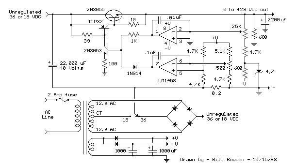
Current and Variable Voltage Power Supply
Another adjustment of application operational amplifiers to adapt a power supply is apparent below. The power supply requires an additional adjustment to supply the op-amps with a bipolar voltage (+/- 8 volts), and the negative voltage is also used to...

Mains Manager
It is common to forget to turn off peripherals such as monitors, scanners, and printers when shutting down a PC. Typically, these devices are connected to a four-way trailing socket, which is plugged into a wall outlet. If this outlet...