


The L200 Datasheet an IC for Voltage and Current Programmable Regulation
#L200
#programmable voltage regulator
#current regulator
#short circuit protection
#battery charger
#motor speed control
#light controller
#high current regulator
#tracking regulator
#NPN pass transistor
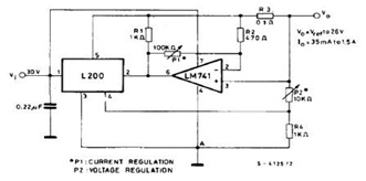
Description: The datasheet contains application circuit diagrams for the L200, including a Programmable Voltage Regulator, a High Current Voltage Regulator with Short Circuit Protection, a Digitally Selected Regulator with Inhibit, a Programmable Voltage and Current Regulator, a High Current Regulator with NPN Pass Transistor, a High Current Tracking Regulator, a Constant Current Battery Charger, a Light Controller, and a 30 W Motor Speed Control.
The L200 is a versatile integrated circuit designed for various voltage regulation applications. The Programmable Voltage Regulator allows for adjustable output voltage levels, making it suitable for a wide range of electronic devices. The High Current Voltage Regulator is particularly notable for its short circuit protection feature, which safeguards the circuit and connected components from damage during fault conditions.
The Digitally Selected Regulator with Inhibit function provides an efficient means of controlling power delivery, allowing the circuit to be enabled or disabled based on digital signals. This feature is especially useful in battery-powered applications where power conservation is essential. The Programmable Voltage and Current Regulator offers dual functionality, enabling precise control over both voltage and current outputs, thus catering to applications requiring strict adherence to power specifications.
The High Current Regulator with NPN Pass Transistor configuration enhances current handling capabilities, making it ideal for high-demand applications. The High Current Tracking Regulator is designed to maintain consistent output voltage levels even as input voltage fluctuates, ensuring stable operation in varying conditions.
For applications requiring constant current delivery, the Constant Current Battery Charger is an excellent choice, providing reliable charging for rechargeable batteries without overcharging risks. The Light Controller enables automated control of lighting systems, enhancing energy efficiency and user convenience. Lastly, the 30 W Motor Speed Control circuit allows for precise regulation of motor speeds, suitable for various industrial and consumer applications.
Each of these circuits can be further explored in the datasheet, which provides detailed schematics, component values, and operational guidelines to aid in implementation and design.In the datasheet, you will see the L200 application circuits diagrams such as Programmable Voltage Regulator, High Current Voltage Regulator with Short Circuit Protection, Digitally Selected Regulator with Inhibit, Programmable Voltage and Current Regulator (click to enlarge figure above), High Current Regulator with NPN Pass Transistor, High Current Tracking Regualtor, Constant Current Battery Charger, Light Controller, and 30 W Motor Speed Control
The L200 is a versatile integrated circuit designed for various voltage regulation applications. The Programmable Voltage Regulator allows for adjustable output voltage levels, making it suitable for a wide range of electronic devices. The High Current Voltage Regulator is particularly notable for its short circuit protection feature, which safeguards the circuit and connected components from damage during fault conditions.
The Digitally Selected Regulator with Inhibit function provides an efficient means of controlling power delivery, allowing the circuit to be enabled or disabled based on digital signals. This feature is especially useful in battery-powered applications where power conservation is essential. The Programmable Voltage and Current Regulator offers dual functionality, enabling precise control over both voltage and current outputs, thus catering to applications requiring strict adherence to power specifications.
The High Current Regulator with NPN Pass Transistor configuration enhances current handling capabilities, making it ideal for high-demand applications. The High Current Tracking Regulator is designed to maintain consistent output voltage levels even as input voltage fluctuates, ensuring stable operation in varying conditions.
For applications requiring constant current delivery, the Constant Current Battery Charger is an excellent choice, providing reliable charging for rechargeable batteries without overcharging risks. The Light Controller enables automated control of lighting systems, enhancing energy efficiency and user convenience. Lastly, the 30 W Motor Speed Control circuit allows for precise regulation of motor speeds, suitable for various industrial and consumer applications.
Each of these circuits can be further explored in the datasheet, which provides detailed schematics, component values, and operational guidelines to aid in implementation and design.In the datasheet, you will see the L200 application circuits diagrams such as Programmable Voltage Regulator, High Current Voltage Regulator with Short Circuit Protection, Digitally Selected Regulator with Inhibit, Programmable Voltage and Current Regulator (click to enlarge figure above), High Current Regulator with NPN Pass Transistor, High Current Tracking Regualtor, Constant Current Battery Charger, Light Controller, and 30 W Motor Speed Control

battery charger regulator
Most commercially available car battery chargers should not be connected to the battery for extended periods, as this can lead to overcharging and subsequent battery damage. This add-on circuit is connected in series with the battery being charged and is...

Put-battery-charger
A short-circuit-proof battery charger provides an average charging current of approximately 8 A to a 12-V lead/acid storage battery. The charger circuit has the additional advantage of being unaffected and undamaged by incorrect battery connections. With an input voltage of...

fixed Current Battery Charger
A simple method of charging a battery from a higher voltage battery is shown in the circuit below to the left. Only one resistor is needed to set the desired charging current and is calculated by dividing the difference in...

Battery charger
A diac is utilized in the gate circuit to enable operation for the signal applied to the gate. R1 sets a threshold level for triggering the triac. C3 and R4 are chosen to restrict the maximum charging current, forming a...
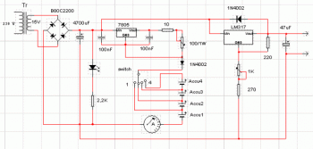
batteries charger and psu circuit
This circuit consists of two main components: a battery charger that provides a fixed output voltage of 5V DC, and a regulated power supply that allows for an adjustable output voltage ranging from 2 to 9 volts.
The circuit design incorporates...

Voltage-controlled cipher scheme of constant-current source of output high-power of bipolar
The output current range of the parameter current regulator is limited, and its precision is not high. Connecting the feedback adjustment type output current of the current-stabilized power source in series results in lower efficiency. The steady current source of...
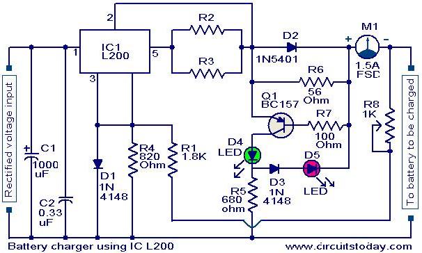
Battery charger circuit using L200
A simple battery charger circuit with reverse polarity indication is presented here. The circuit utilizes the L200 integrated circuit (IC), which is a five-pin variable voltage regulator. The charging circuit can be powered by DC voltage from either a bridge...

Universal-battery-charger
When power is applied to the circuit, SCR1 is off, resulting in no bias current path to ground; thus, LM317 operates as a current regulator. The LM317 is connected to the battery through steering diode D1, limiting resistor R1, and...
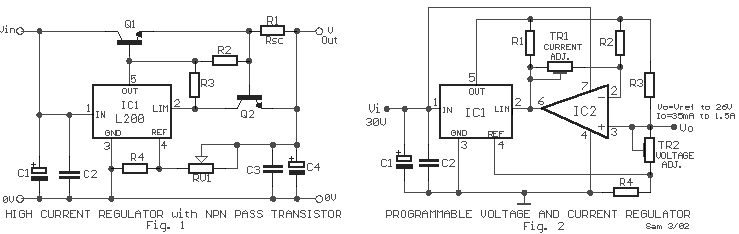
Applications with Voltage Regulator L200 circuit
There are two regulator circuits that utilize the L200 integrated circuit from SGS-Thomson to regulate voltage and current. In circuit Fig. 1, the output voltage can be adjusted using the variable resistor RV1. In Fig. 2, both output voltage and...