


Thyristor AC automatic voltage regulator circuit diagram
#thyristor
#AC voltage
#automatic regulation
#voltage stabilization
#circuit diagram
#power control
#electronic components
#brightness control

Description: The circuit utilizes a thyristor-based AC automatic voltage regulator to stabilize the brightness of lamp L. A diagonal line connects the thyristor to the T5 bridge. The trigger pulse for the thyristor is generated by a single-junction transistor, VT4. Transistors VT1, VT2, and VT3 act as phototransistors, providing equivalent resistance. As the power of the lamp changes, the resistance of the phototransistor also changes, which in turn alters the control voltage of the single-junction transistor. This variation causes a phase shift in the trigger pulse for the thyristor, thereby increasing or decreasing the conduction time of the thyristor. Consequently, the voltage across the lamp remains approximately constant, ensuring stable brightness.
The described circuit is an effective solution for maintaining consistent lamp brightness through the use of a thyristor-based automatic voltage regulator. The thyristor serves as a controlled rectifier that adjusts the amount of power delivered to the lamp based on the feedback from the phototransistor arrangement.
The circuit begins with the AC supply, which is fed into the T5 bridge rectifier. This bridge converts the AC voltage into a pulsating DC voltage suitable for the thyristor's operation. The thyristor, when triggered, allows current to flow through the lamp, and its conduction time is modulated based on the feedback mechanism involving the phototransistors.
The phototransistors (VT1, VT2, VT3) are strategically placed to monitor the light output of the lamp. As the lamp's brightness fluctuates due to changes in load or supply voltage, the phototransistors detect these variations. The change in light intensity results in a corresponding change in their resistance, which affects the voltage at the base of the single-junction transistor (VT4).
The single-junction transistor acts as a control element that generates the trigger pulse for the thyristor. The phase shift of this trigger pulse is crucial; it determines how long the thyristor remains conductive during each AC cycle. By increasing or decreasing the conduction time, the circuit can effectively regulate the average voltage supplied to the lamp.
This feedback loop creates a stable light output, as the system continuously adjusts to maintain the desired brightness. The overall design is efficient and reliable, making it suitable for various applications where consistent lighting is essential. The use of solid-state components like transistors and thyristors enhances durability and reduces maintenance needs compared to mechanical dimming solutions. As shown in the circuit in order to stabilize the lamp brightness L, using thyristor AC automatic voltage regulator circuit. Access to this end a diagonal line from the thyrist or T5 bridge of exchanges. Its trigger pulse is generated by single-junction transistor VT4. Transistor VT1, VT2 and VT3 phototransistor equivalent resistance from the role. When the lamp light power is due to change, the change in resistance of the phototransistor, single-junction transistor control voltage phase also changed, so that the trigger pulse thyristor phase shift, increase or decrease the thyristor conduction time, L on the approximation of the voltage remains constant, the brightness of the lamp is also kept approximately constant, so that the light stability.
The described circuit is an effective solution for maintaining consistent lamp brightness through the use of a thyristor-based automatic voltage regulator. The thyristor serves as a controlled rectifier that adjusts the amount of power delivered to the lamp based on the feedback from the phototransistor arrangement.
The circuit begins with the AC supply, which is fed into the T5 bridge rectifier. This bridge converts the AC voltage into a pulsating DC voltage suitable for the thyristor's operation. The thyristor, when triggered, allows current to flow through the lamp, and its conduction time is modulated based on the feedback mechanism involving the phototransistors.
The phototransistors (VT1, VT2, VT3) are strategically placed to monitor the light output of the lamp. As the lamp's brightness fluctuates due to changes in load or supply voltage, the phototransistors detect these variations. The change in light intensity results in a corresponding change in their resistance, which affects the voltage at the base of the single-junction transistor (VT4).
The single-junction transistor acts as a control element that generates the trigger pulse for the thyristor. The phase shift of this trigger pulse is crucial; it determines how long the thyristor remains conductive during each AC cycle. By increasing or decreasing the conduction time, the circuit can effectively regulate the average voltage supplied to the lamp.
This feedback loop creates a stable light output, as the system continuously adjusts to maintain the desired brightness. The overall design is efficient and reliable, making it suitable for various applications where consistent lighting is essential. The use of solid-state components like transistors and thyristors enhances durability and reduces maintenance needs compared to mechanical dimming solutions. As shown in the circuit in order to stabilize the lamp brightness L, using thyristor AC automatic voltage regulator circuit. Access to this end a diagonal line from the thyrist or T5 bridge of exchanges. Its trigger pulse is generated by single-junction transistor VT4. Transistor VT1, VT2 and VT3 phototransistor equivalent resistance from the role. When the lamp light power is due to change, the change in resistance of the phototransistor, single-junction transistor control voltage phase also changed, so that the trigger pulse thyristor phase shift, increase or decrease the thyristor conduction time, L on the approximation of the voltage remains constant, the brightness of the lamp is also kept approximately constant, so that the light stability.

Lamp automatic exchange regulator circuit schematic
The circuit is designed to stabilize the brightness of lamp L using a thyristor-based AC automatic voltage regulator. The thyristor T5 is connected diagonally across the bridge circuit. The trigger pulses are generated by components VT1, VT2, and VT3, which...

loewe f875 sensotronic chassis f800 11
The LOEWE F875 SENSOTRONIC CHASSIS 543/490 is based on the F800 LOEWE chassis series and functions similarly to a color television chassis, featuring an EHT output with a tripler and horizontal output utilizing thyristor technology. The LOEWE-OPTA start-delay overload protection...

thyristor trigger circuit schematic diagram
The circuit receives its input from the zero-crossing detector, which generates a 0-to-1-to-0 pulse to set the R-S flip-flop and activate the ramp circuit (A to Ramp) to initiate the timing ramp ascent.
The described circuit operates by utilizing a zero-crossing...

Bidirectional thyristor AC contactor interface circuit
Device for an intermediate relay. The circuit utilizes a Triac AC contactor interface, employing the MOC3041 Triac output optical coupler to trigger the Triac. When Pl0 is low, the Triac will be activated, energizing the AC contactor coil.
The described device...

As one of the thyristor type delay circuit
This circuit is a thyristor-based delay circuit known as a cut-off delay. It allows for a specified delay period after the thyristor is activated. The delay time of the circuit can be adjusted within 10 seconds by changing the resistor...
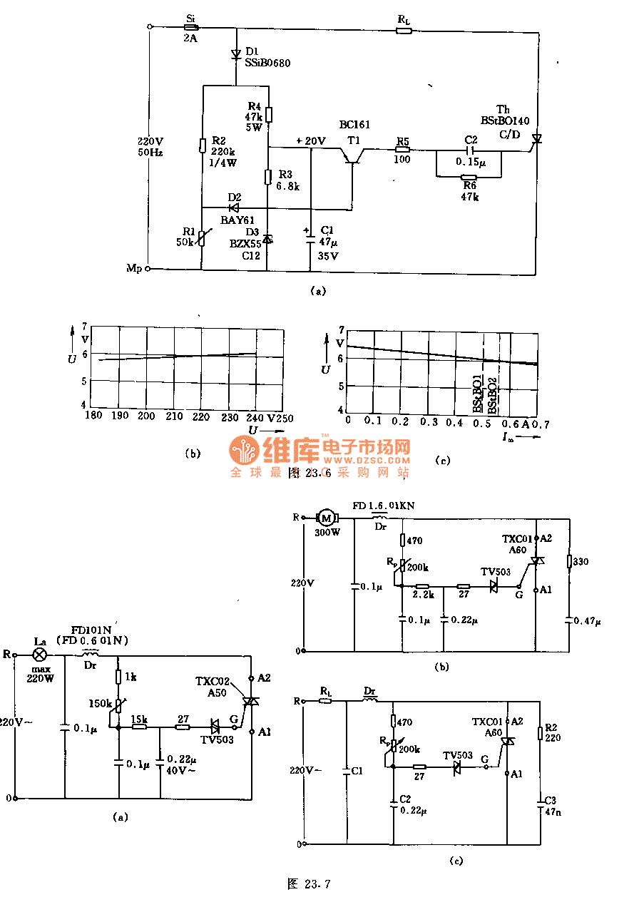
Thyristor circuit with 100W 700W and 1000W output power
This is a non-contact power regulator circuit designed for a light load. By adjusting a 150kΩ potentiometer, phase shift can be achieved, and a trigger voltage is applied to the gate of a bidirectional thyristor through a bidirectional trigger to...

Line operated thyristor control time delay
This circuit utilizes a CA3059 or CA3079 zero-voltage switch to manage the turn-on timing of a triac. The delay between the closure of the switch and the activation of the triac is determined by the resistor (R) and capacitor (C)...
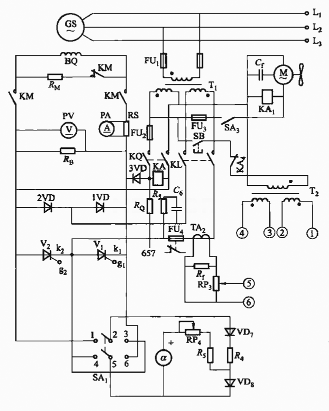
FKL-32 type automatic thyristor excitation circuit
The FKL-32 type automatic thyristor excitation device is designed for synchronous generators with a terminal voltage of 400V and a capacity of 500kW or below. It is used for the automatic adjustment of excitation.
The FKL-32 automatic thyristor excitation device plays...

Three single-phase motor stepless thyristor circuits
The circuit illustrated in Figure 3-12 incorporates variable speed and timing control functions. When switch S is set to position 1 and button SB is pressed, the motor initiates operation. After a predetermined delay, the motor automatically shuts down. The...