


transformer How can I get 17 VDC from 25 VDC with current may up to 10 A
#voltage reduction
#high current
#diode bridge
#capacitor
#voltage divider
#power supply
#DC-DC conversion
#10A circuit
#25VDC
#17VDC
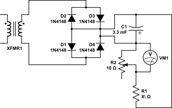
Description: Connect the 25VAC output to a diode bridge with a capacitor (3300uF - 25V) to the positive and negative pins to eventually obtain 25VDC. The goal is to reduce the 25VDC to 17VDC. A voltage divider with a variable resistor was considered for this purpose, but it appears that the 10A current damaged the resistor.
To convert 25VAC to 17VDC, a suitable approach involves using a diode bridge rectifier followed by a smoothing capacitor. The diode bridge consists of four diodes arranged in a bridge configuration, allowing for full-wave rectification of the AC input. The capacitor (3300uF - 25V) serves to smooth out the rectified voltage, reducing ripple and providing a more stable DC output.
To achieve the desired output voltage of 17VDC from the 25VDC, a more robust voltage regulation method is recommended rather than a simple voltage divider, especially given the high current of 10A. A linear voltage regulator or a switching regulator would be more appropriate for this application. For instance, a linear regulator such as the LM317 can be employed, configured to output 17V by adjusting the resistor values according to the formula provided in the datasheet.
Alternatively, a buck converter could be utilized, which is more efficient for high current applications. This method steps down the voltage while maintaining high efficiency, thus avoiding the overheating issues associated with resistive voltage dividers. Proper heat sinking and thermal management should also be considered when implementing these components to ensure reliable operation under load.
In summary, transitioning from 25VDC to 17VDC in a high-current application necessitates the use of a more robust voltage regulation technique, such as a linear regulator or a buck converter, rather than a voltage divider, which is prone to failure under significant load conditions.Connect the 25VAC output to diodes bridge with capacitor (3300uF - 25v) to the positive and negative pins to eventually get 25VDC. What I want is to reduce the 25VDC to 17VDC, I thought i could build voltage divider with variable resistor to get the volt I want, but it looks like the passed 10amp damaged the resistor.
To convert 25VAC to 17VDC, a suitable approach involves using a diode bridge rectifier followed by a smoothing capacitor. The diode bridge consists of four diodes arranged in a bridge configuration, allowing for full-wave rectification of the AC input. The capacitor (3300uF - 25V) serves to smooth out the rectified voltage, reducing ripple and providing a more stable DC output.
To achieve the desired output voltage of 17VDC from the 25VDC, a more robust voltage regulation method is recommended rather than a simple voltage divider, especially given the high current of 10A. A linear voltage regulator or a switching regulator would be more appropriate for this application. For instance, a linear regulator such as the LM317 can be employed, configured to output 17V by adjusting the resistor values according to the formula provided in the datasheet.
Alternatively, a buck converter could be utilized, which is more efficient for high current applications. This method steps down the voltage while maintaining high efficiency, thus avoiding the overheating issues associated with resistive voltage dividers. Proper heat sinking and thermal management should also be considered when implementing these components to ensure reliable operation under load.
In summary, transitioning from 25VDC to 17VDC in a high-current application necessitates the use of a more robust voltage regulation technique, such as a linear regulator or a buck converter, rather than a voltage divider, which is prone to failure under significant load conditions.Connect the 25VAC output to diodes bridge with capacitor (3300uF - 25v) to the positive and negative pins to eventually get 25VDC. What I want is to reduce the 25VDC to 17VDC, I thought i could build voltage divider with variable resistor to get the volt I want, but it looks like the passed 10amp damaged the resistor.

Saving voltage regulator circuit
This document presents a power-saving voltage regulator circuit. In addition to its general function as a delay regulator, the circuit features: (1) an automatic voltage regulation capability for mains voltage within a range of 220V ±10%, allowing direct power supply...

High Current 13.8V Power Supply
As is commonly the case, this supply was born of necessity. There is absolutely nothing special about the circuit, except that as shown, it is quite capable of up to 20 Amps intermittently or 10A continuous. Simply use a bigger...

Power Supply for P.A. Class40
For its maximum result, the final stage of the amplifier should have the proper power supply, as the flowing currents are very high. A Class A amplifier requires attention. These are the rules for the power supply for the Class...

The second phase alarm circuit
A capacitor C1 and resistors R1-R3 form a negative sequence voltage filtration device. The resistors and capacitors must meet the following requirements: R1, R2, R3 = 5.5/C1 (KN). The relationship between the resistance and capacitance values is arbitrary. Capacitor selection...

Capacitor charging and discharging
Large-value capacitors are necessary for this experiment to generate time constants slow enough to be monitored with a voltmeter and stopwatch. It is important to note that most large capacitors are of the "electrolytic" type, which are sensitive to polarity....

adj pwr
The design incorporates a universal capacitor mounting and spacing feature, enabling compatibility with various capacitor types. It includes a mounting pattern suitable for TO-200 or TO-218/247 packages, specifically for the pass transistor and the transistor utilized in the current limit...

Battery charger or Power Supply 14 volt 4 ampere
The schematic diagram originates from a circuit designed as a battery charger/power supply with an output of 14V and a maximum current of 4A, utilizing the VN64GA MOSFET. This high-performance battery charger is specifically engineered for gelled electrolyte lead-acid batteries,...

Switching power supply drive circuit
Driver circuit diagram: The primary function of the driver circuit is to serve as a variable width pulse width modulator output power amplifier, providing a drive signal to high voltage power switching devices. The driving circuit typically plays a role...

Batteries charger & PSU - ideal for digital camerass
This circuit was designed for digital cameras, which are known to have significant power consumption. For instance, the Minolta E223 camera requires approximately 800 mA. In practice, this demand can be met using a mains power supply or high-capacity NiMH...