


pic RN-41 bluetooth module not transmitting data
#bluetooth
#PIC microcontroller
#RN-41
#voltage divider
#transistors
#3.3V logic
#5V logic
#PCB design
#data transmission
#wireless communication

Description: Connect a PIC microcontroller to an RN-41 Bluetooth module. The PCB was not designed by the current user, so the rationale behind the circuit's design, which differs from the voltage divider method used by others, is unclear. The 5V logic from the PIC microcontroller is used to control transistors connected to a 3.3V source, effectively converting the signal to 3.3V levels. An issue arises when this is connected to the RX pin of the RN-41 SparkFun breakout board, resulting in the signal being driven to ground (indicated by a flatline on the oscilloscope). There is a possibility that the RX pin is shorted to ground, or the chip may have been damaged. In a different setup, using a slightly modified version of the transistor and another RN-41 chip, the 3.3V logic does not go to ground, and a 3.3V logic signal is observed on the RX pin; however, the paired device does not receive any data. The purpose of the MAX232 chip in the circuit is uncertain. Additionally, the components in question are not LM-50s but rather generic transistors with a similar physical appearance. The source is connected to a 3.3V regulator, the gate is connected to the RS-232 output, and the drain connects to the RX pin of the RN-41 module. It is noted that there was an initial error where the MAX232 chip was not powered at VCC; this has been rectified by soldering a wire from VCC to the nearest power inlet connected to 5V.
The circuit connects a PIC microcontroller with a 5V logic level to an RN-41 Bluetooth module, which operates at 3.3V. The use of transistors serves as a level shifter, allowing the higher voltage logic to control the lower voltage module. In this configuration, the PIC's output is routed through a transistor, where the source is connected to a 3.3V regulator, the gate is driven by the output of the RS-232 interface, and the drain connects to the RX pin of the RN-41.
The observed issue of the RX pin being driven to ground suggests a potential short circuit or damage to the RN-41 module. This can be diagnosed by checking the RX pin for continuity to ground and verifying the integrity of the module. In the alternate setup, where a different transistor configuration is used, the 3.3V logic level appears correctly on the RX pin, indicating that the transistors are functioning properly. However, the lack of data transmission to the paired device may require further investigation into the Bluetooth pairing process or signal integrity.
The inclusion of the MAX232 chip is typically for level shifting RS-232 signals to TTL levels, but its necessity in this design could be questioned if the primary function of the communication does not require such level shifting. If the MAX232 is present but not powered, it could lead to unreliable operation, which has been addressed by ensuring it is properly connected to the power supply.
In conclusion, careful examination of the circuit connections, component functionality, and signal integrity is essential for troubleshooting the communication issues between the PIC microcontroller and the RN-41 Bluetooth module.Connect a pic to an rn-41 bluetooth module. I`m not the person who designed the PCB, so I can`t answer exactly why the circuit is the way that it is instead of using the voltage divider used by some other people. Basically, the 5v logic from the pic is used to control transistors which are connected to a 3. 3v source (converting it to 3. 3v levels). The only issue is that when I connect this to the Rx pin of the rn-41 sparkfun breakout board, suddenly the signal is completely driven to ground (flatline on the o-scope). Is it possible the Rx pin is shorted to ground, or the chip might have been fried Further, on a different setup using a slightly different version of the transistor and a separate bluetooth rn-41 chip (we have two rn-41s) the 3.
3v logic is not driven to ground, and a 3. 3v logic signal is seen on the Rx pin. however the device it is paired with does not receive anything. (I`m not ENTIRELY sure why the max232 is even there. ) ALSO, those aren`t LM-50s. they`re just transistors with the same physical shape. the source is connected to a 3. 3v regulator. the gate is connected to the output of the rs232, and the drain goes to the rx pin of the rn-41 (the chip at the very bottom) note that it has 1 mistake which we already fixed: the max232 chip is not connected to power @ vcc. we fixed that already by soldering a wire from vcc to the nearest inlet connected to power (5v).
The circuit connects a PIC microcontroller with a 5V logic level to an RN-41 Bluetooth module, which operates at 3.3V. The use of transistors serves as a level shifter, allowing the higher voltage logic to control the lower voltage module. In this configuration, the PIC's output is routed through a transistor, where the source is connected to a 3.3V regulator, the gate is driven by the output of the RS-232 interface, and the drain connects to the RX pin of the RN-41.
The observed issue of the RX pin being driven to ground suggests a potential short circuit or damage to the RN-41 module. This can be diagnosed by checking the RX pin for continuity to ground and verifying the integrity of the module. In the alternate setup, where a different transistor configuration is used, the 3.3V logic level appears correctly on the RX pin, indicating that the transistors are functioning properly. However, the lack of data transmission to the paired device may require further investigation into the Bluetooth pairing process or signal integrity.
The inclusion of the MAX232 chip is typically for level shifting RS-232 signals to TTL levels, but its necessity in this design could be questioned if the primary function of the communication does not require such level shifting. If the MAX232 is present but not powered, it could lead to unreliable operation, which has been addressed by ensuring it is properly connected to the power supply.
In conclusion, careful examination of the circuit connections, component functionality, and signal integrity is essential for troubleshooting the communication issues between the PIC microcontroller and the RN-41 Bluetooth module.Connect a pic to an rn-41 bluetooth module. I`m not the person who designed the PCB, so I can`t answer exactly why the circuit is the way that it is instead of using the voltage divider used by some other people. Basically, the 5v logic from the pic is used to control transistors which are connected to a 3. 3v source (converting it to 3. 3v levels). The only issue is that when I connect this to the Rx pin of the rn-41 sparkfun breakout board, suddenly the signal is completely driven to ground (flatline on the o-scope). Is it possible the Rx pin is shorted to ground, or the chip might have been fried Further, on a different setup using a slightly different version of the transistor and a separate bluetooth rn-41 chip (we have two rn-41s) the 3.
3v logic is not driven to ground, and a 3. 3v logic signal is seen on the Rx pin. however the device it is paired with does not receive anything. (I`m not ENTIRELY sure why the max232 is even there. ) ALSO, those aren`t LM-50s. they`re just transistors with the same physical shape. the source is connected to a 3. 3v regulator. the gate is connected to the output of the rs232, and the drain goes to the rx pin of the rn-41 (the chip at the very bottom) note that it has 1 mistake which we already fixed: the max232 chip is not connected to power @ vcc. we fixed that already by soldering a wire from vcc to the nearest inlet connected to power (5v).
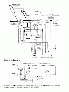
BlueTooth Ericofon
It would be impressive to sit at a favorite coffee shop with an Ericofon on the table. While chatting with friends, the phone rings, and upon picking it up, one hears a dial tone and uses the rotary dial to...

McCAD PCB software
McCAD E.D.S software, a complete family of integrated electronic designs systems for MS Windows and Macintosh OS platforms. McCAD Electronic Design Systems offer a choice of design environments with a wide range of system configurations tailored to the specific needs...

A Beginners Guide to Microchip PIC Microcontroller Programming
A simple program that will blink an LED. All that is required is a basic JDM programmer, and the setup is ready to go. The circuit requires a power supply, and while a good power generator is recommended, a simple...

Interface Bluetooth with LPC2148 circuit
The interfacing of a Bluetooth module with the LPC2148 microcontroller is a straightforward process that enables the transmission of messages from the LPC2148 Primer Board to mobile devices via Bluetooth using UART0. Some delays may occur when sending a single...

0-24v digital variable power supply circuit
The following circuit diagram depicts a variable power supply controlled by a PIC microcontroller. An LCD display is utilized to show the actual output current and voltage values. This digital power supply incorporates a push-button switch to adjust the output...

pic based modified sine wave inverter
A PIC-based inverter circuit is being developed that utilizes two P-channel MOSFETs (F9540N) along with a center-tapped 12-0-12/230V transformer.
The proposed circuit design incorporates a microcontroller from the PIC family, which serves as the main control unit for the inverter operation....

Interface a HD44780 Character LCD with a PIC Microcontroller
An HD44780 Character LCD is a liquid crystal display (LCD) device designed for interfacing with embedded systems. These screens are available in various configurations, including 8x1 (one row of eight characters), 16x2, and 20x4. The most commonly produced configuration is...

Pulsonix PCB
Innovative yet easy-to-use PCB design editor. Includes many leading edge features for the casual and professional designer alike. Pulsonix contains a complete set of tools for designing Schematics and PCB designs in one integrated interface. Able to import many other...

Hidden Radio Transmitter Controller
PicCon is a PIC microcontroller based radio controller designed for hidden transmitter hunting. When combined with a radio transmitter, it will produce tone sequences and Morse code messages at user-programmed times. It is completely field programmable via DTMF tones, utilizes...