


Wireless Interface RF Modules Circuit
#RF modules
#transmitter
#receiver
#18F452
#18F4520
#data communication
#wireless interface
#microcontroller

Description: The RF modules utilized in this schematic are straightforward, requiring only a few additional pins for power, ground, and data connections. The primary components featured in this schematic include the RF transmitter module, the RF receiver module, and the microcontrollers 18F452 and 18F4520. Both circuits necessitate a power supply circuit, which is identical for each. An LM7805 voltage regulator takes battery input and steps it down to +5V. A DC filtering capacitor is employed to eliminate noise from the +5V output. The distinction between the two circuits lies in the data lines: the receiver connects to the RX pin (PORTC 7) on the PIC, while the transmitter connects to the TX pin (PORTC 6). These data lines interface with the respective data pins on the transmitter and receiver modules, which are responsible for transmitting data between the two units with minimal error. The subsequent theory section will explore how the receiver module can be modified to mitigate distortion.
The schematic comprises two primary RF modules, one for transmission and the other for reception, operating on a shared power supply derived from a regulated +5V output. The LM7805 voltage regulator is a linear voltage regulator that efficiently converts higher battery voltages to a stable +5V, which is essential for the reliable operation of the RF modules and microcontrollers. The inclusion of a DC filtering capacitor serves to smooth out any voltage fluctuations and noise, ensuring that the RF modules receive clean power, which is critical for maintaining signal integrity.
The RF transmitter module is responsible for encoding and sending data wirelessly, while the RF receiver module decodes the incoming signals. The microcontrollers, 18F452 and 18F4520, are programmed to manage the data flow between the transmitter and receiver, utilizing the designated TX and RX pins for communication. The TX pin (PORTC 6) sends data from the microcontroller to the transmitter module, which modulates the data onto a carrier wave for transmission. Conversely, the RX pin (PORTC 7) receives the modulated signal from the receiver module, which demodulates the signal back into a format that the microcontroller can process.
The design emphasizes minimizing data transmission errors, which is crucial in RF communication. The use of the respective data pins ensures that the microcontrollers can effectively control the data flow, while the RF modules handle the wireless communication. Future modifications to the receiver module may include error correction techniques to further enhance the reliability of the data transmission, addressing potential distortions that may occur during the wireless transfer. This comprehensive approach facilitates robust communication between the two circuits, making it suitable for various applications in wireless data transmission.The RF modules used in this schematic are very simple, with only a few extra pins required for power, ground and data. The main parts used in this schematic are the RF transmitter module, RF receiver module, 18F452 and 18F4520.
You can see them below, as well as the specific circuits described in more detail. Since there are two seperate circu its, both need to have a power supply circuit. The power supply in both circuits is identical, a LM7805 takes battery input and regulates it down to +5v. The DC filtering capacitor cleans up any noise off the +5v output. The only difference for this part of the circuit is that the receiver uses the RX pin (PORTC 7) on the PIC and the transmitter uses the TX pin (PORTC 6) on the PIC.
Both of these data lines connect to the data pin on the transmitter or receiver module. These two modules are in charge of passing the data from one link to the other without adding too much error. We`ll see later in the theory section how the receiver module can be altered to help correct distortion.
The schematic comprises two primary RF modules, one for transmission and the other for reception, operating on a shared power supply derived from a regulated +5V output. The LM7805 voltage regulator is a linear voltage regulator that efficiently converts higher battery voltages to a stable +5V, which is essential for the reliable operation of the RF modules and microcontrollers. The inclusion of a DC filtering capacitor serves to smooth out any voltage fluctuations and noise, ensuring that the RF modules receive clean power, which is critical for maintaining signal integrity.
The RF transmitter module is responsible for encoding and sending data wirelessly, while the RF receiver module decodes the incoming signals. The microcontrollers, 18F452 and 18F4520, are programmed to manage the data flow between the transmitter and receiver, utilizing the designated TX and RX pins for communication. The TX pin (PORTC 6) sends data from the microcontroller to the transmitter module, which modulates the data onto a carrier wave for transmission. Conversely, the RX pin (PORTC 7) receives the modulated signal from the receiver module, which demodulates the signal back into a format that the microcontroller can process.
The design emphasizes minimizing data transmission errors, which is crucial in RF communication. The use of the respective data pins ensures that the microcontrollers can effectively control the data flow, while the RF modules handle the wireless communication. Future modifications to the receiver module may include error correction techniques to further enhance the reliability of the data transmission, addressing potential distortions that may occur during the wireless transfer. This comprehensive approach facilitates robust communication between the two circuits, making it suitable for various applications in wireless data transmission.The RF modules used in this schematic are very simple, with only a few extra pins required for power, ground and data. The main parts used in this schematic are the RF transmitter module, RF receiver module, 18F452 and 18F4520.
You can see them below, as well as the specific circuits described in more detail. Since there are two seperate circu its, both need to have a power supply circuit. The power supply in both circuits is identical, a LM7805 takes battery input and regulates it down to +5v. The DC filtering capacitor cleans up any noise off the +5v output. The only difference for this part of the circuit is that the receiver uses the RX pin (PORTC 7) on the PIC and the transmitter uses the TX pin (PORTC 6) on the PIC.
Both of these data lines connect to the data pin on the transmitter or receiver module. These two modules are in charge of passing the data from one link to the other without adding too much error. We`ll see later in the theory section how the receiver module can be altered to help correct distortion.
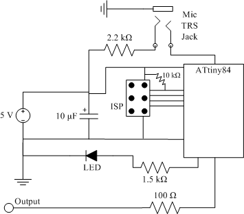
clap sensor construction
The clap sensor is a straightforward circuit that consists of a PC microphone, a microcontroller, and an output. The circuit design features the ATtiny84 microcontroller, chosen for familiarity with the AVR architecture and accessibility to necessary tools. The ATtiny84 is...

Microcontroller-based automatic night light circuit
While discussing an all-linear automatic night light circuit, it was mentioned that an MCU-based Automatic Night Light Controller (ANLC) was being tested. The firmware has been tweaked since then. Recently, the sensor was installed outdoors and connected to control 220VAC...

14W CW TRANSMITTER
A low-power two-stage FET transmitter designed for the 80-meter amateur band utilizes a Pierce crystal oscillator that does not require an output resonant circuit. A DC milliammeter can be connected across a 150-ohm resistor in the gate circuit of the...

A8V W8EXI 6CL6 One Tube Transmitter
A8V W8EXI 6CL6 One Tube Transmitter. The operation of the 6CL6 transmitter is actually quite sophisticated.
The A8V W8EXI 6CL6 One Tube Transmitter is a compact and efficient radio frequency (RF) transmitter that utilizes a single 6CL6 vacuum tube for its...

Atv Jr Transmitter 440Mhz Circuit
This low-power video transmitter is designed for remote control (R/C) applications, surveillance, or amateur radio purposes. It utilizes seven transistors within a crystal oscillator-multiplier RF power amplifier chain, along with a high-level video modulator. A supply voltage of 9 to...

Industrial Building Automation System (IBAS) - 4
The two optical sensors will provide a count of individuals to the microcontroller, which will relay this value to MCU-II. The microcontroller will detect the entrance of any person through high-to-low pulse transitions on input pins A3 and A4.
The circuit...

1929 MOPA 80 meter transmitter using a pair of 27 triodes to an 865 tetrode
This transmitter originated as a conventional shunt-fed Hartley oscillator for 80 meters, utilizing a pair of 27 triodes connected in parallel. With 300 VDC applied to the plates of the 27s, it produced approximately 4 watts of output with decent...

MCU controlled Bluetooth automation
The microcontroller used is 0822 zilog encore! 8k series (soic,28pin) as shown on the figure. Is a programmable microcontroller, the functions used are the GPIO and the UART of the chip. GPIO is used on led indicators, and the UART...

TV transmitter circuit using only 2 transistors operates from 12V
A simple two-transistor TV transmitter circuit that operates from 12V. It is compatible with PAL B and PAL G systems.
The described circuit utilizes two transistors to create a basic television transmission system capable of operating on a 12V power supply....