
control motor controller stepper

The described circuit utilizes a microcontroller to control a stepper motor via a digital interface. The implementation of a buffer is crucial for protecting the microcontroller from excessive current and voltage levels that may be encountered during motor operation. The buffer can be realized using either a traditional buffer IC or a FET, each with its advantages in terms of input impedance and switching characteristics.
In the case of using a transistor buffer, it is essential to select a power transistor with a suitable current rating to match the requirements of the stepper motor. The pull-up resistor value must be chosen to ensure that the base current is sufficient to drive the transistor into saturation, allowing it to handle the load current effectively. The gain of the transistor plays a significant role in determining how much collector current can be supplied, making it critical to choose a transistor with adequate gain for the application.
Alternatively, employing a FET such as the IRL540 provides a robust solution for high-current applications. The FET's ability to handle significant current and voltage levels makes it suitable for driving stepper motors directly. The open-collector configuration allows for easy integration with the microcontroller, while the FET's high input impedance minimizes the load on the microcontroller's output pins.
In both configurations, incorporating a capacitor across the motor terminals can mitigate voltage spikes that occur during the switching process, thereby protecting the circuit components from potential damage. Proper thermal management through the use of heat sinks is also vital to ensure reliable operation under load conditions. Overall, careful consideration of component selection and circuit design will lead to an efficient and effective stepper motor control system.If control circuit of this driver motor in the form of microcontroller or digital component hence it is better that every port controlling network driver this stepper motor given buffer before hand in order not to encumber port microcontroller applied. Like at picture 3, pin control_0, control_1, control_2 and this control_3 can be controlled digitally by using microcontroller by giving functioning
component as buffer like at this picture: At picture is only be presented one parts to control one fruit of motor bobbin stepper. There is two alternatives that is by using former buffer or applies FET, what has a real input impedance height, as the switches component.
Tension V motor is not must always equal to tension VCC at microcontroller. On that account applied by a buffer component having output open collector so that the output earns in pull-up to tension wanted. For election base of the transistor is at characteristic IC (collector current). This transistor must be transistor power capable to overcome current as according to current required by this stepper motor bobbin.
If current pulled by motor bobbin stepper simply bigger than abilities of transistor hence transistor would quickly hot and can cause the breakdown the transistor. R pull-up 470 will give current 10 mA to transistor bases Q1. If Q1 had gain 1000 hence current which can be via is around some amperes, depended from big of current pulled by stepper motor bobbin.
This current have to be more be small from current IC enabled. For component FET can be applied component IRL540 which can flow current to 20 Ampere and can arrest back tension until 100V. This thing because of by this FET can permeate tension spike without protection of diode. But this component requires heat sink which is big and must be good enough in the case of absorbs of the temperature.
It is better if it is applied capacitor to depress level tension spike generated from transition of switches from on to OFF. 🔗 External reference
Related Circuits

The switching action of the 2N4990 enables the use of smaller capacitors while ensuring reliable triggering of thyristors. The 2N4990 is a high-speed switching transistor that plays a crucial role in applications requiring efficient control of thyristors. The device's rapid...
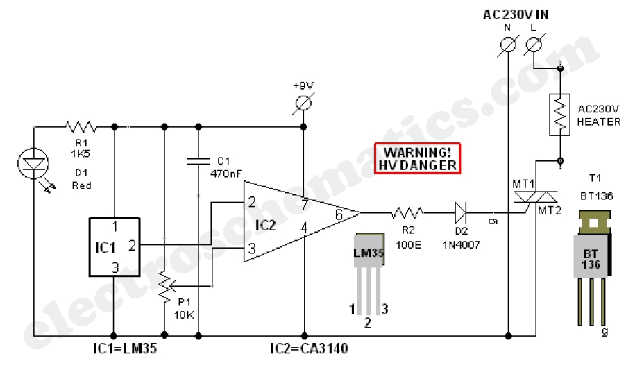
The compact circuit of the electric AC heater controller is designed around the well-known 3-Pin Integrated Temperature Sensor LM35 (IC1) from National Semiconductor Corporation (NSC). The circuit utilizes the LM35 temperature sensor, which provides an analog output voltage that is...

A simple single-transistor circuit provides an approximate 15 dB boost at 100 Hz and a 15 dB cut at 15 kHz. A low-noise audio transistor is utilized, and the output can be directly connected to any existing amplifier volume...

The circuit consists of a 555 timer IC configured as a multivibrator, which operates with two probes to measure the water level. When the capacitance between the probes indicates a high water level, the output from the 555 timer...

This Remote control Jammer device is useful when blocking someone from using the remote control (such as children who frequently change the channels on the TV). This remote control jammer is very simple and uses two infrared LEDs that...
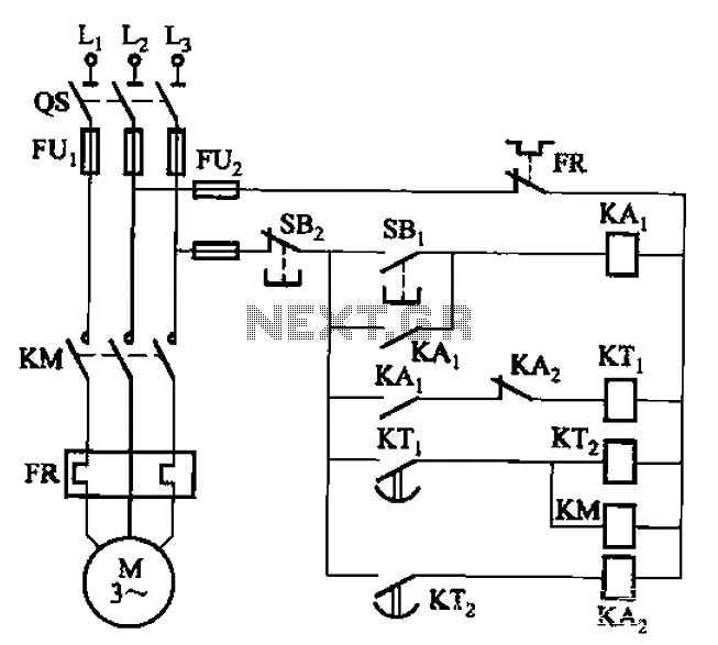
The circuit illustrated in Figure 3-76 employs two time relays, KTi and KTz, to manage the operation and downtime of a motor. The circuit utilizes two time relays to provide precise control over the motor's operational cycles. Relay KTi is...