NE558N
NE558N Quad Timer Technical Summary
Overview
The NE558N is a monolithic quad timer IC designed for precision timing applications. It provides four entirely independent timing functions in a single package, making it ideal for systems requiring multiple timing operations. The device is highly stable and can be configured in monostable (one-shot) mode to generate accurate time delays ranging from microseconds to hours. The timing period is precisely controlled by an external resistor and capacitor network, offering flexibility in design.
With its robust design and wide operating voltage range, the NE558N serves as a versatile solution for various timing and control applications across industrial, automotive, and consumer electronics sectors.
Features
- Quad Timer Configuration: Four independent timing sections in a single package
- Wide Supply Voltage Range: Operates from 4.5V to 16V DC
- High Output Current: Capable of sinking or sourcing 100mA per section
- Precision Timing: Time period equals RC product for accurate delay generation
- Edge-Triggered Operation: No coupling capacitor required for triggering
- Independent Outputs: Each timer output is unaffected by other sections' trigger conditions
- Monostable Operation: Configurable for precise time delay generation
- Stable Mode Capability: Can be configured for oscillator operation
Applications
Primary Applications
- Quad one-shot pulse generation
- Sequential timing systems
- Precision delay generation
- Industrial timing controllers
Secondary Applications
- Automotive timing circuits
- Consumer electronics timing functions
- Test equipment timing modules
- Security system delay circuits
- Process control timing
Electrical Characteristics
Absolute Maximum Ratings
- Supply Voltage (VCC): 18V
- Input Voltage (any input): VCC + 0.3V
- Output Current (per section): 100mA
- Total Power Dissipation: 600mW
- Operating Temperature Range: 0°C to +70°C
- Storage Temperature Range: -65°C to +150°C
Recommended Operating Conditions
- Supply Voltage Range: 4.5V to 16V
- Input Trigger Pulse Width: ≥ 100ns
- Timing Capacitor Range: 100pF to 100μF
- Timing Resistor Range: 1kΩ to 10MΩ
- Operating Free-Air Temperature: 0°C to 70°C
Electrical Characteristics (VCC = 5V, TA = 25°C unless otherwise noted)
- Supply Current (all sections idle): 10mA max
- Output Low Voltage (IOL = 50mA): 0.4V max
- Output High Voltage (IOH = -50mA): 2.75V min
- Trigger Voltage: 1.4V min, 1.6V max
- Trigger Current: 0.5μA max
- Reset Voltage: 0.7V max
- Reset Current: 0.5mA max
- Timing Error: ±2% typical
Package Information
Physical Specifications
- Package Type: 16-pin DIP (Dual In-line Package)
- Package Material: Molded Plastic
- Lead Material: Solder-plated Copper Alloy
- Package Dimensions: 19.3mm x 6.35mm x 4.57mm
- Lead Pitch: 2.54mm (0.1 inch)
- Weight: Approximately 1.2 grams
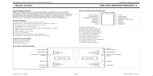
Pin Configuration
- Pin 1: Timer A Output
- Pin 2: Timer A Trigger Input
- Pin 3: Timer A Reset Input
- Pin 4: Timer A Threshold/Discharge
- Pin 5: Timer B Threshold/Discharge
- Pin 6: Timer B Reset Input
- Pin 7: Timer B Trigger Input
- Pin 8: Timer B Output
- Pin 9: Ground
- Pin 10: Timer C Output
- Pin 11: Timer C Trigger Input
- Pin 12: Timer C Reset Input
- Pin 13: Timer C Threshold/Discharge
- Pin 14: Timer D Threshold/Discharge
- Pin 15: Timer D Reset Input
- Pin 16: VCC (Positive Supply Voltage)
Functional Description
The NE558N contains four independent timer circuits that are functionally equivalent to the popular 555 timer IC. Each timer section operates in monostable (one-shot) mode, where the timing period is determined by an external resistor and capacitor connected to the threshold/discharge pin. The output pulse width is precisely equal to 1.1 × R × C, providing accurate timing control.
Each timer section features:
- A trigger input that initiates the timing cycle on a falling edge
- A reset input that can prematurely terminate the output pulse
- An open-collector output capable of sinking substantial current
- A threshold/discharge terminal for connecting the timing network
The four timer sections share common power supply connections but otherwise operate completely independently, allowing for complex timing sequences and multiple concurrent timing operations.
Design Considerations
Timing Component Selection
For accurate timing operation, use stable, low-leakage components for the timing network. Film capacitors are recommended for timing values below 1μF, while tantalum or aluminum electrolytic capacitors can be used for larger values. Timing resistors should have a tolerance of 1% or better for precision applications.
Power Supply Decoupling
A 0.1μF ceramic capacitor should be placed as close as possible between VCC (pin 16) and ground (pin 9) to minimize power supply noise and ensure stable operation, especially when driving inductive loads or in electrically noisy environments.
Output Loading
While each output can sink up to 100mA, simultaneous operation of all four outputs at maximum current may exceed the package's total power dissipation limits. For continuous high-current operation, consider using external drivers or heat sinking.