
DC motor control using 555 timer circuit

The circuit employs the 555 timer in astable mode, which generates a pulse-width modulation (PWM) signal to control the average voltage supplied to the DC motor. The frequency and duty cycle of the PWM signal are determined by the values of the resistors and the potentiometer connected to the timer.
In this setup, the 50 kΩ potentiometer is connected in series with a fixed resistor, creating a voltage divider that influences the timing characteristics of the 555 timer. As the potentiometer is adjusted, the resistance changes, altering the width of the pulses generated by the timer. This, in turn, changes the effective voltage applied to the DC motor, allowing for smooth speed control.
The DC motor is connected to the output of the 555 timer through a suitable transistor or MOSFET, which acts as a switch to handle the higher current required by the motor. A diode should be placed in parallel with the motor terminals to protect the circuit from back EMF generated when the motor is turned off.
Power supply for the circuit should be stable and capable of providing the necessary voltage and current for both the 555 timer and the DC motor. Proper decoupling capacitors are recommended to filter out any noise in the power supply lines.
This 555 timer motor control circuit is ideal for applications where variable speed is needed, such as in robotics, fans, or other motor-driven devices. The simplicity of the design, combined with the effectiveness of PWM control, makes it a popular choice among hobbyists and engineers alike.Using this 555 timer DC motor control electronic project you can control speed of a 6 volts DC motor, by simply rotate left or right the 50 k potentiometer. 🔗 External reference
Related Circuits

Classic 555 timer chip schematic circuit t-shirt by EEVblog picture on VisualizeUs - bookmark pictures and videos that inspire you. Social bookmarking of pictures and videos. Find your pictures and videos. The 555 timer IC is a versatile and widely...

Automatic volume adjustment with ambient noise control circuit. In car stereos and similar devices, the ambient noise level varies during high-speed and low-speed driving or while stationary, leading to different volume requirements. A fixed volume adjustment method may negatively...

To program an AVR microcontroller using a USB port instead of parallel or serial interfaces, USBasp is the most suitable option. A circuit diagram for USBasp is available. The procedure for burning the hex file includes installing avrdude (WinAVR),...

This document discusses the series used in USB connections for charging batteries. The output voltage ranges from 4.7 volts to 5 volts DC, which is suitable for charging mobile phones and other battery types. The circuit described enhances the...

When the lights of an oncoming car are detected by the photo-transistor Q1, the circuit activates. Sensitivity is adjusted by the 22-megohm resistor, R5, to approximately half a foot-candle. The relay employed has a 12-volt, 0.3A coil. The L14C1...
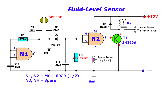
The circuit diagram presented illustrates the MC14093B Fluid Level Sensor Circuit. It is characterized by its compact and simple design, utilizing a single-chip configuration suitable for a wide range of applications. The MC14093B is a CMOS quad two-input NAND gate...