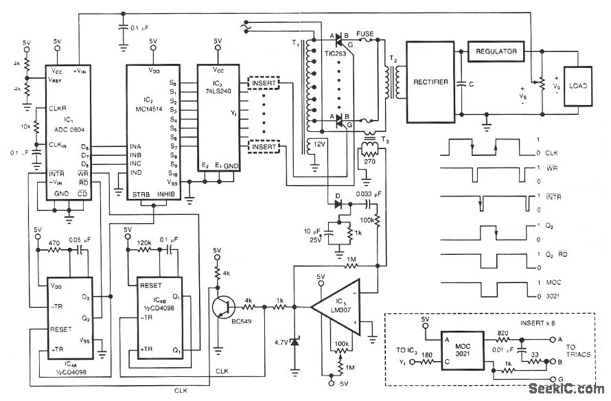
MOC3021 Connection Diagram

The MOC3021 is an optically isolated triac driver device. This device contains a GaAs infrared emitting diode and a light-activated silicon bilateral switch, which operates similarly to a triac. It is designed for interfacing between electronic controls and power triacs to control resistive and inductive loads for 240 VAC operations.
The MOC3021 serves as an essential component in various applications where electrical isolation between control and power circuits is necessary. The opto-isolation provided by the GaAs infrared emitting diode ensures that the control side remains electrically separate from the high-voltage side, enhancing safety and reliability in circuit design.
The device's internal structure includes an infrared LED that, when activated by a control signal, emits light that triggers the silicon bilateral switch. This switch behaves like a triac, enabling it to conduct current in both directions, which is particularly useful for alternating current (AC) applications. The MOC3021 can handle a load voltage of up to 240 VAC, making it suitable for various household and industrial applications, such as motor control, lighting, and heating systems.
The MOC3021 is typically used in conjunction with a power triac, allowing for the control of high-power devices while minimizing the risk of damage to sensitive electronic components. The opto-isolator's ability to manage both resistive and inductive loads makes it versatile for numerous applications. Furthermore, the device's compact package and ease of integration into printed circuit boards (PCBs) facilitate its adoption in modern electronic designs.
In summary, the MOC3021 is a robust solution for applications requiring electrical isolation and control of high-voltage AC loads, combining the benefits of opto-isolation with the functionality of a triac in a single package.The MOC3021is optically isolated triac driver devices. These devices contain a GaAs infrared emitting diode and a light activated silicon bilateral switch, which functions like a triac. They are designed for interfacing between electronic controls and power triacs to control resistive and inductive loads for 240 VAC operations
🔗 External reference


