
Triac temperature sensitive heater control

The described circuit utilizes a triac to regulate temperature-sensitive heating elements by controlling the power delivered to them. The triac functions as a switch that can be turned on and off rapidly, allowing for precise control over the heater's output. The temperature sensing is typically achieved using a thermistor or a thermocouple, which provides feedback to the control circuit based on the ambient temperature.
In the heating configuration, the circuit operates by monitoring the temperature and adjusting the conduction angle of the triac accordingly. As the temperature rises above a set threshold, the control circuit reduces the power to the heater to maintain the desired temperature. Conversely, when the temperature drops below the threshold, the control circuit increases the power, allowing the heater to operate at full capacity until the set point is reached again.
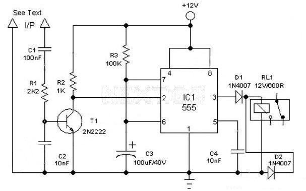
When modified for motor control, the same principles apply. The circuit can be adapted to control the speed of a motor with a constant load by adjusting the power delivered to the motor. This can be particularly useful in applications where precise speed control is necessary, such as in fans or pumps. The interchange of RT and R2 allows for the reconfiguration of the circuit, enabling it to switch from a heating application to a cooling application, thus providing versatility.
In both configurations, the circuit design must incorporate appropriate safety features, such as over-temperature protection and current limiting, to prevent damage to the components and ensure reliable operation. Additionally, proper heat sinking for the triac may be necessary to dissipate heat generated during operation, particularly in high-power applications.Triac temperature-sensitive heater control. This circuit can be modified as shown to control a motor with a constant load. As shown the circuit is for heating applications but can be used for cooling by interchanging RT and R2 (courtesy Motorola Semiconductor Products Inc. ). 🔗 External reference
Related Circuits
This circuit illustrates a lighting control circuit diagram with a power rating of approximately 300-350W. Features include low cost, simplicity, and operation at 120V AC voltages. Components: .. The lighting control circuit designed for 300-350W applications is intended to provide...

This project is a digital Automatic Gain Control (AGC) system using a PIC16F876 MCU. The ability to set the gain level in a circuit and have it control itself is a very useful function. This circuit is a building...

This compact circuit is designed to control model railway turnouts that operate using AC voltages. A control signal within the range of 5 to 12 volts can be utilized. The turnout coils are activated by triacs. Variations in the...

After restoring its engine and other mechanical components to optimal condition, the next step involved adding aesthetic lighting. A visit to a local electronics store resulted in the discovery of 12V DC-operated LED strips, which were ideal for the...

A servo motor is a specialized geared DC motor that includes an electronic circuit for controlling the direction and position of the motor shaft. Due to its capability for precise angular positioning, servo motors are widely utilized in robotics,...
This is a simple automatic light switch circuit designed for bedrooms. After construction, connect the input terminals of this circuit in parallel to the internal buzzer terminals of a quartz alarm clock. When the clock alarm is activated, the...