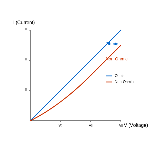
DC Parallel Circuit
1. Definition and Characteristics of DC Parallel Circuits
1.1 Definition and Characteristics of DC Parallel Circuits
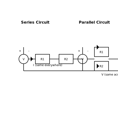
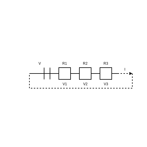
In electrical engineering, a DC parallel circuit refers to a configuration of circuit elements where the voltage across each component remains the same while the current can differ. This fundamental circuit configuration contrasts with series circuits, wherein the same current flows through all components, leading to distinct behaviors and applications.
The most pivotal characteristic of a parallel circuit is that each component is connected directly to the voltage source. As a result, if one branch of the circuit fails (e.g., an open switch or a burned-out resistor), the remaining branches continue to function. This is exemplified in real-world applications such as household wiring systems, where multiple lights can operate independently without affecting the others.
Key Characteristics of DC Parallel Circuits
- Equal Voltage Distribution: All components in a parallel circuit share the same voltage across their terminals. For instance, if a parallel circuit is connected to a 12V battery, every component receives 12V.
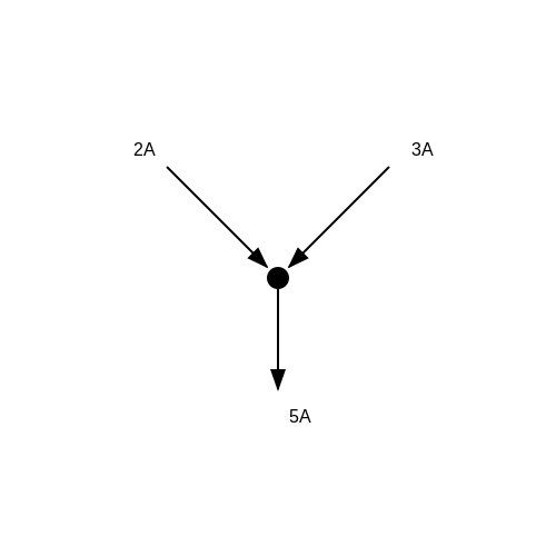
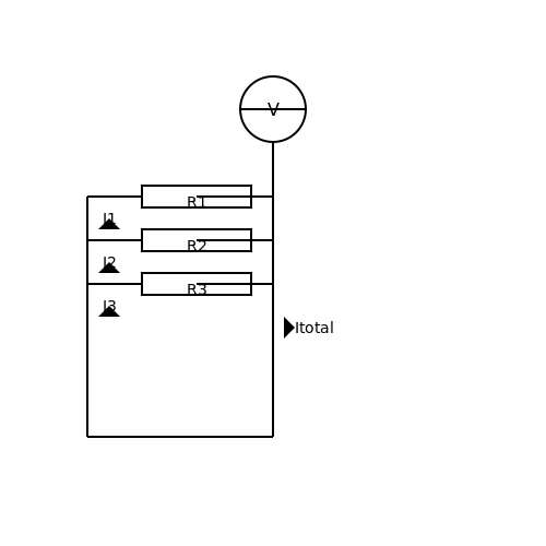
- Current Division: The total current flowing from the source is divided among all paths in the circuit. The total current can be expressed mathematically as:
Here, \( I_{total} \) is the total current supplied by the voltage source, while \( I_1, I_2, I_3, \) and so on, represent the individual currents flowing through the respective components.
- Resistance Calculation: The overall resistance of a parallel circuit is not merely the sum of the individual resistances. Instead, the reciprocal of the total resistance \( R_{total} \) can be calculated as follows:
This leads to an essential aspect of parallel circuits: when more components are added, the total resistance decreases, thus increasing the total current drawn from the source.
Implications and Real-World Applications
The implications of DC parallel circuits are profound in various domains, particularly in power distribution systems and electronics. For instance, when designing battery packs for electric vehicles, parallel configurations allow for increased current capability while maintaining the same voltage, enhancing efficiency and performance. Moreover, parallel circuits are prevalent in printed circuit boards (PCBs), where electronic components operate simultaneously and independently, leading to more reliable and robust designs.
In conclusion, understanding the definition and characteristics of DC parallel circuits is crucial for engineers and physicists alike, informing the design and analysis of complex electronic systems.
1.2 Basic Components: Resistors, Voltage Sources, and Connectors
In a DC parallel circuit, the interaction of fundamental components shapes the overall characteristics and functionality of the circuit. This section delves into three critical elements: resistors, voltage sources, and connectors. Each component's role is pivotal in ensuring that a parallel circuit operates efficiently, offering insights into their theoretical and practical significance.
Resistors
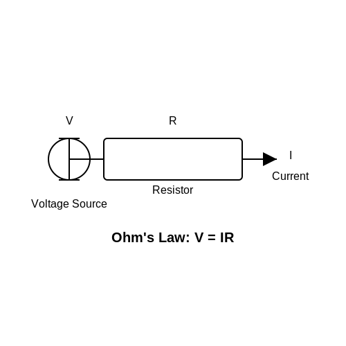
Resistors are passive components that limit the flow of electric current in a circuit. Their primary function is to manage voltage drops and current levels according to Ohm's Law, which states that the current (I) flowing through a conductor between two points is directly proportional to the voltage (V) across the two points, given by the equation:
Where R is the resistance measured in ohms (Ω). when used in parallel configurations, the behavior of resistors becomes particularly interesting, as the total or equivalent resistance (Req) can be derived from the formula:
This equation reveals that the equivalent resistance of resistors connected in parallel is always less than the smallest resistor in the network, leading to increased total current capacity. For practical applications, understanding the behavior of resistors in parallel is crucial for designing circuits that require specific current loads without exceeding player limitations.
Voltage Sources
In a parallel configuration, multiple voltage sources can be employed, typically sharing the same voltage level. The voltage across each component connected in parallel remains constant and equivalent to the source voltage, represented by:
One practical application is in battery packs, where multiple cells are connected in parallel to maintain a consistent voltage while increasing the overall capacitance and discharge potential. This configuration is frequently used in renewable energy systems, where battery performance and reliability are paramount. An insight into the operational characteristics of the voltage sources helps ensure optimal performance under varying load conditions.
Connectors
The role of connectors in a DC parallel circuit cannot be understated, as they facilitate secure and reliable electrical connections between components. The choice of connectors significantly influences the circuit's overall performance, including aspects such as resistance, inductance, and potential voltage drop across connections. Copper and aluminum connectors are common due to their high conductivity, while the mechanical design must accommodate the physical requirements of the circuit layout.
When designing circuits that utilize multiple connectors, it's crucial to minimize contact resistance and ensure robust physical and electrical connectivity to mitigate issues like overheating or signal loss. Additionally, connectors need to be rated for the appropriate current and voltage levels to ensure safety and reliability in operations. In practice, engineers often conduct thorough testing to validate connector performance under operational stresses, leading to optimal configurations that enhance circuit efficacy.
In summary, understanding the basic components of resistors, voltage sources, and connectors is foundational for the design and implementation of DC parallel circuits. Engineers and physicists can utilize this knowledge in a variety of applications, from consumer electronics to industrial systems, making the mastery of these components a necessity in the field of electronics.
1.3 Voltage and Current Distribution in Parallel Circuits
The ability to understand voltage and current distribution in a direct current (DC) parallel circuit is critical for engineers and researchers involved in electronics design and analysis. In parallel circuits, the configuration allows for multiple paths through which current can flow, leading to distinctive characteristics in how voltage and current are distributed across components. This subsection builds upon fundamental circuit theory and explores the implications of these characteristics in practical systems.
Voltage Characteristics in Parallel Circuits
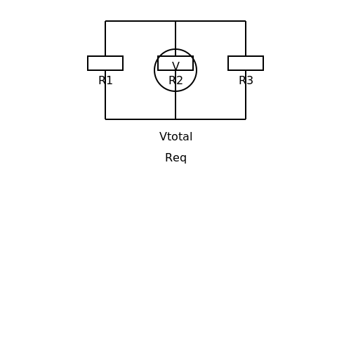
One of the essential properties of a parallel circuit is the voltage across each component. In a parallel configuration, all connected components directly share the same two nodes. Thus, the voltage across each component is equal to the voltage supplied by the source. Mathematically, this can be expressed as:
where \(V\) is the total voltage from the power source, and \(V_1, V_2, \ldots, V_n\) are the voltages across each of the \(n\) components in the circuit. This principle guarantees that the voltage remains constant across all components, ensuring that each device operates effectively without the variability found in series circuits.
Practical Examples of Voltage in Parallel Circuits
In real-world applications, such as in residential wiring systems, light fixtures connected in parallel are a common illustration of this concept. Even though different light bulbs may have varying resistances, they receive the same voltage from the electrical supply. This arrangement assures uniform brightness and functionality across all fixtures.
Current Distribution in Parallel Circuits
Unlike voltage, current distribution in a parallel circuit is not uniform. The total current supplied by the source divides among the parallel branches based on the resistance of each component. Ohm’s law forms the cornerstone of this understanding, with the current through each branch defined as:
where \(I_n\) is the current flowing through the \(n^{th}\) component, \(R_n\) is its resistance, and \(V\) is the voltage across the component (which we established is equal to the source voltage). Consequently, the total current in the circuit can be calculated using Kirchhoff's current law, yielding:
The distribution of current across the branches illustrates that components with lower resistance will draw more current than those with higher resistance. This principle signifies that careful consideration must be taken during circuit design to ensure that components can handle their respective currents without overheating or failing.
Real-World Applications of Current Division
The concept of current distribution is particularly critical in battery management systems (BMS) for electric vehicles. In such systems, cells are often connected in parallel to provide higher capacity. Understanding and optimizing current distribution through each cell is essential to prolonging battery life and ensuring safety.
Conclusion
In summary, the voltage and current distribution in parallel circuits fundamentally differs due to their unique configuration. Understanding the constancy of voltage across multiple components and the division of current based on individual resistances is essential for effective circuit design. This knowledge is not only theoretical but has practical implications across various industries.
2. Applying Ohm's Law to Parallel Circuits
2.1 Applying Ohm's Law to Parallel Circuits
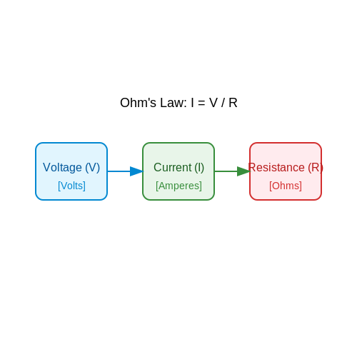
In electrical engineering and physics, understanding the interaction between voltage, current, and resistance is pivotal for analyzing circuits. Ohm's Law, which states that the voltage (V) across a conductor is directly proportional to the current (I) flowing through it, and inversely proportional to the resistance (R), serves to underpin the analysis of both series and parallel circuits:Understanding Voltage in Parallel Circuits
In parallel circuits, the voltage across each component remains constant and is equal to the source voltage. This is a key feature of parallel configurations that fundamentally alters the application of Ohm's Law in comparison to series circuits. Therefore, if a circuit is supplied by a voltage source \( V_s \), each resistor \( R_i \) will satisfy the equation:Current Distribution and Total Resistance
The current, however, varies across the different parallel branches. By applying Ohm's Law at individual resistors, we can express the current through each resistor as:Practical Relevance
Understanding how to apply Ohm's Law in parallel circuits is crucial across numerous applications, especially in power distribution systems and electronic devices where multiple components share the same voltage supply. In practice, this knowledge informs the design of systems that require redundancy, reliability, and efficiency—such as the development of battery packs where every cell operates in parallel. Moreover, this principle becomes fundamentally significant in the design of modern electronic devices, where different components might need to operate under varying conditions of load while sharing the same power supply. A practical example includes parallel lighting circuits in household electrical systems where individual lights can be independently turned on or off without disrupting the entire circuit flow. In summary, applying Ohm's Law to parallel circuits encapsulates the comprehensive understanding necessary to tackle complex electrical scenarios. As we proceed to the next section, we will further explore the implications of these fundamental principles in troubleshooting and optimizing parallel circuit configurations.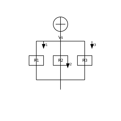
2.2 The Parallel Resistor Formula
The concept of resistors in parallel is fundamental in both theoretical and practical electronics. Understanding how to calculate the equivalent resistance can dramatically simplify the analysis of complex circuits found in various applications such as power distribution systems, audio equipment, and sensor networks.Understanding Parallel Resistance
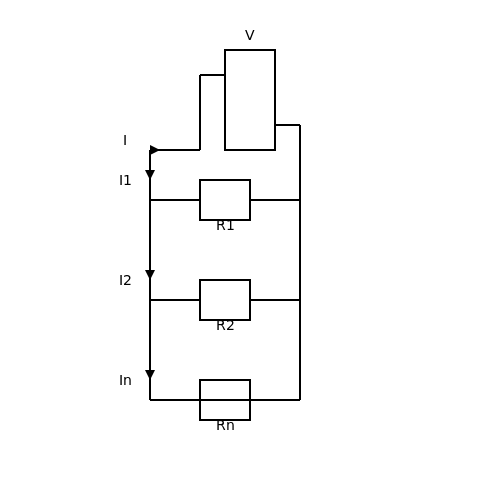
In a parallel configuration, resistors are connected across the same two nodes, thereby sharing the same voltage differential. This setup results in each resistor offering an independent path for current, thus allowing for a higher system conductivity. The main consequence of this configuration is that the total or equivalent resistance is always less than the smallest individual resistor in the network. For advanced analysis, consider a system of resistors \( R_1, R_2, R_3, \ldots, R_n \) connected in parallel. The current flowing through each resistor can be visualized as emerging from a common voltage source and distributed among the resistive paths.Deriving the Parallel Resistor Formula
To derive the formula for equivalent resistance in parallel, we start with Ohm's Law, which states that voltage (\( V \)) is equal to the product of current (\( I \)) and resistance (\( R \)). In a parallel circuit, the voltage across each resistor is the same: \[ V = I_1 R_1 = I_2 R_2 = I_3 R_3 = \ldots = I_n R_n \] Where \( I_1, I_2, \ldots, I_n \) are the currents through resistors \( R_1, R_2, \ldots, R_n \). The total current \( I_{total} \) flowing from the voltage source is the sum of the currents through each resistor: \[ I_{total} = I_1 + I_2 + I_3 + \ldots + I_n \] Substituting for each individual current using Ohm's Law, we have: \[ I_{total} = \frac{V}{R_1} + \frac{V}{R_2} + \frac{V}{R_3} + \ldots + \frac{V}{R_n} \] Factoring out the common voltage \( V \), we arrive at: \[ I_{total} = V \left( \frac{1}{R_1} + \frac{1}{R_2} + \frac{1}{R_3} + \ldots + \frac{1}{R_n} \right) \] Applying Ohm's Law again to express the total equivalent resistance \( R_{eq} \): \[ V = I_{total} R_{eq} \] By substituting the expression for \( I_{total} \) we derived: \[ V = V \left( \frac{1}{R_1} + \frac{1}{R_2} + \frac{1}{R_3} + \ldots + \frac{1}{R_n} \right) R_{eq} \] Since \( V \) is common (and non-zero), we can simplify this to: \[ \frac{1}{R_{eq}} = \frac{1}{R_1} + \frac{1}{R_2} + \frac{1}{R_3} + \ldots + \frac{1}{R_n} \] This leads us to the formula for equivalent resistance in a parallel circuit:Practical Applications
The principles of parallel resistances extend beyond basic circuits. For instance, in power systems, parallel connections are utilized to distribute loads more effectively among multiple power sources. In audio electronics, multiple speaker systems can be configured in parallel to achieve a desired sound profile with controlled impedance levels. Advantages in modular electronic designs also leverage the parallel resistor configurations to optimize performance and reliability. Furthermore, modern electronic systems often integrate parallel resistors within embedded circuits to mitigate heat generated by excess current. This practice not only enhances thermal management but also contributes to overall system efficiency. As you delve deeper into circuit analysis, understanding the implications of the parallel resistor formula will enable you to approach complex networks with confidence and clarity.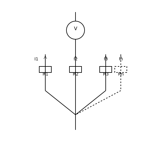
2.3 Techniques for Circuit Analysis: Nodal and Mesh Analysis
In the realm of electronic circuit design, particularly when dealing with DC parallel circuits, effective analysis techniques are paramount. Two of the most prevalent methods utilized in circuit analysis are Nodal Analysis and Mesh Analysis. Each method offers distinct advantages, making them suited for different scenarios. This section aims to explore both techniques in detail, elucidating their procedural applications, theoretical underpinnings, and practical relevances.Nodal Analysis
Nodal Analysis serves as a systematic approach to determine the voltage levels at various points (nodes) within a circuit. The fundamental principle underlying this method is Kirchhoff's Current Law (KCL), which states that the algebraic sum of currents entering a node must equal the sum of currents leaving that node. To apply Nodal Analysis, one typically follows these steps: 1. Identify all nodes in the circuit: Designate one node as a reference node (often referred to as the ground) and assign voltage variables (e.g., V1, V2,..., Vn) to the other nodes. 2. Apply KCL at each node: For each non-reference node, express the current in terms of node voltages using Ohm's Law (I = V/R). This leads to a set of simultaneous equations. 3. Solve the system of equations: Utilize methods such as substitution, elimination, or matrix operations to solve for the unknown node voltages. Let’s illustrate this with a fundamental example where three resistors R1, R2, and R3 are connected in parallel between a voltage source, V, and the ground. By establishing node references and applying KCL: - At node V1, if I1 is the current through R1, I2 is the current through R2, and I3 is the current through R3, we express currents as: $$ I_1 = \frac{V_1 - V}{R_1}, \quad I_2 = \frac{V_1 - 0}{R_2}, \quad I_3 = \frac{V_1 - 0}{R_3} $$ Applying KCL at node V1: $$ \frac{V_1 - V}{R_1} + \frac{V_1}{R_2} + \frac{V_1}{R_3} = 0 $$ Rearranging gives: $$ V_1 \left(\frac{1}{R_1} + \frac{1}{R_2} + \frac{1}{R_3}\right) = \frac{V}{R_1} $$ From here, we can directly solve for \( V_1 \): $$ V_1 = \frac{\frac{V}{R_1}}{\frac{1}{R_1} + \frac{1}{R_2} + \frac{1}{R_3}} = \frac{V R_2 R_3}{R_2 R_3 + R_1 R_3 + R_1 R_2} $$Mesh Analysis
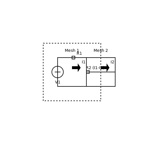
Mesh Analysis, on the other hand, is based on Kirchhoff's Voltage Law (KVL), which states that the sum of the electrical potential differences (voltages) around any closed network is zero. This method proves efficacious particularly in planar circuits. To implement Mesh Analysis effectively, consider the following: 1. Identify meshes in the circuit: A mesh is defined as a loop that does not enclose any other loops. Label each mesh with a current (e.g., I1, I2,..., Im). 2. Apply KVL to each mesh: For each independent mesh, sum up the voltage drops across elements and set equal to zero. 3. Solve the resulting equations: Similar to Nodal Analysis, one might employ substitution, elimination, or matrix techniques. For context, let us envision a circuit composed of two loops containing resistors R1, R2, and a common voltage source V. By applying KVL around each loop, one may derive: For the first mesh (containing \(R_1\) and the source): $$ -V + I_1 R_1 + I_2 R_2 = 0 $$ For the second mesh (containing \(R_2\)): $$ I_2 R_2 - I_1 R_2 = 0 $$ These can be rearranged to find the currents in terms of the source voltage and the resistors' values. Real-world applications of Nodal and Mesh Analysis enable engineers to evaluate complex systems with multiple elements, like power distribution systems, control systems, and electronic devices. Mastery of these analytical techniques not only enhances circuit design but also contributes towards optimizing performance and reliability in electronic products.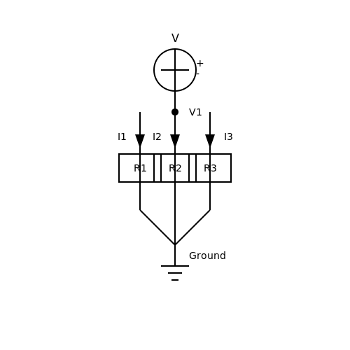
3. Common Uses in Household and Industrial Circuits
3.1 Common Uses in Household and Industrial Circuits
The significance of DC parallel circuits extends across various domains, from household appliances to complex industrial systems. A parallel circuit configuration allows multiple components to connect across the same voltage source, thereby ensuring uniform voltage across each element while independently varying the current. This flexibility has led to a variety of applications that enhance efficiency and functionality in both domestic and industrial settings.Household Applications
In residential settings, the most prevalent application of DC parallel circuits is found within electronic devices that necessitate a seamless power supply to multiple operations. Devices like LED lighting systems, for instance, exemplify this utility. When LEDs are arranged in parallel, the failure of one LED does not interrupt the circuit; the remaining bulbs continue functioning, which is critical for maintaining lighting in essential areas. Another significant application is in computer power supplies. Modern computers contain multiple components, including processors, motherboards, and storage devices that all require stable voltage for optimal performance. In a parallel configuration, each component receives the necessary voltage while drawing the current it requires. This setup also contributes to the reliability of the system: if one component experiences a fault, the others can continue to operate. Furthermore, battery systems often utilize DC parallel circuits to achieve greater total current capacity while maintaining the same voltage level. For example, connecting several batteries in parallel can enhance the overall current available, allowing for extended usage of devices without altering the voltage specifications critical for performance.Industrial Applications
In the industrial landscape, DC parallel circuits are essential for ample reasons, particularly in applications requiring uninterrupted power delivery and system reliability. Telecommunications equipment, for instance, commonly employs parallel circuit designs to provide backup power. Here, batteries are connected in parallel to ensure that critical telecommunication services remain operational, even when primary power sources fail. Similarly, renewable energy systems such as solar power setups often incorporate parallel circuit configurations. Solar panels connected in parallel allow for optimal performance even when some panels experience shading or faults. This configuration maximizes the output by ensuring that each panel operates at the same voltage, enhancing the overall energy harvest. The industrial sector also leverages DC parallel circuits in applications like motor control systems. These systems may require multiple motors to operate simultaneously while independent current regulation is needed for each motor's unique load. By designing the circuitry in parallel, operators can ensure consistent control over each motor, improving both flexibility and reliability in operations.Conclusion
In summary, DC parallel circuits serve a pivotal role across various applications both at home and in the industry. Their innate ability to sustain voltage levels while allowing individual current variation makes them essential in designs aimed at maximizing reliability and efficiency. Understanding these applications deepens the appreciation of their function, illuminating the critical role they play in sustaining modern electronic and electrical systems. Exploring further, one could delve into the future innovations in circuit designs that harness this understanding to create even more efficient electrical systems.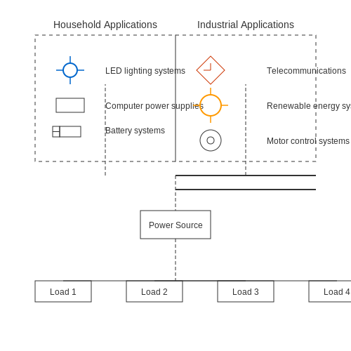
3.2 Advantages and Disadvantages of Parallel Circuits
Understanding the advantages and disadvantages of DC parallel circuits is pivotal for engineers, physicists, and researchers engaged in circuit design and analysis. Parallel circuits, where components are connected across common voltage points, have unique characteristics compared to series circuits that directly influence their application in various domains.
Advantages of Parallel Circuits
The parallel configuration presents several significant benefits:
- Constant Voltage: In a parallel circuit, all components receive the same voltage, making them suitable for ensuring that devices operating at a specific voltage function correctly.
- Independent Operation: If one component fails, the others continue to operate without interruption. This attribute is crucial in critical applications such as safety systems and industrial controls.
- Multi-Branch Systems: Adding more branches increases total current capacity while maintaining the same voltage level, which is particularly useful in power distribution networks.
- Simplified Troubleshooting: Because each component operates independently, identifying faults becomes easier, allowing for more efficient maintenance and repair.
Disadvantages of Parallel Circuits
Despite their benefits, parallel circuits also present some disadvantages that must be considered:
- Complex Design: The configuration can lead to increased complexity in circuit design due to the multiple pathways for current flow, which may complicate the calculation of total resistance.
- Higher Current Draw: As more components are added, the total current drawn from the supply increases, potentially exceeding the maximum current capacity of the source and causing failure.
- Voltage Division Risks: While each component receives the same voltage, uneven load distribution can lead to overheating or damage if not managed properly, especially in heavier load scenarios.
- Power Consumption: Inefficient parallel configurations may lead to higher overall power consumption due to increased current flow, which may not be ideal in power-sensitive applications.
In practical real-world applications, the choice between parallel and series configurations often depends on the specific needs of the system. For example, most residential wiring utilizes parallel configurations because it allows appliances to operate independently and maintain consistent voltage, mirroring the need for reliability and efficiency in modern circuits.
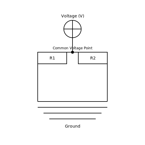
3.3 Designing Parallel Circuits: Best Practices
When designing DC parallel circuits, a thorough understanding of their operational principles and nuanced design considerations is essential. The parallel configuration presents unique advantages, such as enhanced reliability and adaptability in load distribution, thereby necessitating a strategic approach to design that incorporates best practices.Understanding Load Distribution
One of the primary considerations in parallel circuit design is load distribution. In a parallel setup, each load (or resistor) is connected directly to the voltage source. This configuration allows for *individual load operation*; each component receives the same voltage while the current divides inversely according to their resistive values. Consequently, maximizing performance requires insightful resistor placement and selection to ensure that current sharing is optimized. To quantify the effect of resistors in parallel, we can derive the equivalent resistance \( R_{eq} \) using the formula:Account for Current Path Limitations
Next, ensure that the current paths are adequately sized. Overlooked aspects of circuit design, such as wire gauge and series resistance, can lead to inconsistent performance or overheating due to excessive current flow. Ohm's law can guide appropriate wire selection to prevent voltage drop across the wiring, which is often neglected in larger circuits. For practical applications, consider the American Wire Gauge (AWG) standards that suggest permissible current levels based on the wire diameter. Choose wires that minimize resistance while maintaining the necessary flexibility and insulation.Utilize Circuit Breaker and Fuse Protection
As currents flow through a parallel circuit, it becomes crucial to integrate protective components, such as circuit breakers or fuses. These devices serve as a safeguard against overload conditions, which can result in fire hazards or circuit failure. When designing these protections: - Ensure that the ratings exceed the normal operating range but are still below levels that would cause damage to your components. - Calculate expected maximum current based on total circuit load and comfort levels of each individual component.Simulation for Optimal Performance
Simulation tools have become invaluable resources in modern electrical engineering design. Software platforms like SPICE can help simulate circuit behaviors under various conditions, validating component selection and the overall circuit function. Testing designs virtually before implementing them physically can reduce iteration time and resource costs significantly. In summary, designing efficient parallel circuits entails:- Thorough understanding of load distribution.
- Proper sizing of current paths.
- Implementation of protective devices.
- Utilization of simulation tools for validation.
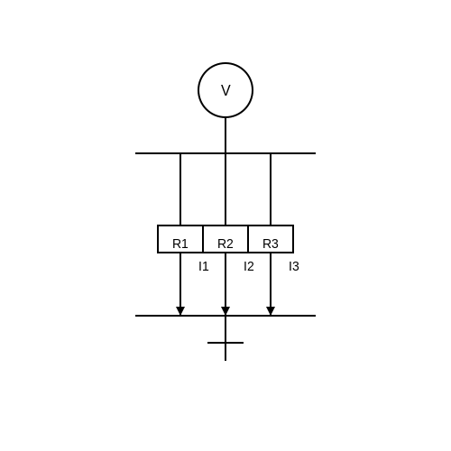
4. Common Faults in Parallel Circuits
4.1 Common Faults in Parallel Circuits
Understanding the Nature of Parallel Circuits
In a parallel circuit, components are connected across common voltage points, ensuring that each component experiences the same voltage while the current may vary. This design is prevalent in household wiring and electronic devices due to its advantages in maintaining voltage consistency. However, this configuration can lead to several common faults that, if not addressed, can result in faulty operations, increased energy consumption, or even hazardous situations.Identifying Key Faults
Understanding the main faults in parallel circuits begins with recognizing their causes and effects. Let's explore some of the most prevalent issues that may arise:- Open Circuit: This occurs when a connection is severed at any point in the circuit, leading to a complete loss of current across one or more branches. For instance, if a light bulb burns out in a parallel circuit, other bulbs remain operational because they share the same voltage source.
- Short Circuit: A fault that may occur when a branch of the parallel circuit offers little to no resistance, effectively bypassing the intended load. This scenario can lead to excessive current flowing, which may damage components or create fire hazards. In practical applications, fuses or circuit breakers are implemented to mitigate this risk.
- Unequal Current Distribution: Due to variations in resistance among paths in the circuit, unequal current distribution can lead to overheating or component failure. This imbalance can stem from poor connections, defective components, or inherent resistance differences. Engineers employ Wattmeters and ammeters to monitor these levels and diagnose issues promptly.
- Ground Fault: A situation where a live wire contacts the ground, creating a risky current path. Ground faults are critical concerns, especially in environments where moisture is present. Ground fault circuit interrupters (GFCIs) are used in residential wiring to detect and disconnect the circuit quickly, promoting safety.
Mathematical Approach to Analyzing Faults
To reinforce our understanding, let’s derive some fundamental relations inherent to current distribution in parallel circuits. The total current, \( I_{\text{total}} \), provided by the source is the summation of the individual branch currents, \( I_1, I_2, \ldots, I_n \): $$ I_{\text{total}} = I_1 + I_2 + \ldots + I_n $$ If the resistances of the branches are \( R_1, R_2, \ldots, R_n \), then using Ohm's law, the branch currents can be expressed in terms of the total voltage \( V \): $$ I_k = \frac{V}{R_k} \quad \text{for } k = 1, 2, \ldots, n $$ Plugging this back into the current summation gives: $$ I_{\text{total}} = \frac{V}{R_1} + \frac{V}{R_2} + \ldots + \frac{V}{R_n} = V \left( \frac{1}{R_1} + \frac{1}{R_2} + \ldots + \frac{1}{R_n} \right) $$ The overall resistance \( R_{\text{total}} \) of the parallel circuit can thus be derived from: $$ \frac{1}{R_{\text{total}}} = \frac{1}{R_1} + \frac{1}{R_2} + \ldots + \frac{1}{R_n} $$ This relational understanding lays the groundwork for diagnosing faults by using measurements of branch currents and total resistance.Practical Implications of Faults
In real-world applications, recognizing and rectifying these issues is vital for reliability and safety. Engineers often utilize diagnostic tools such as oscilloscopes for oscillatory faults, multimeters for resistance checks, and thermal cameras to observe overheating components. Knowledge of these potential faults not only enhances design practices but also informs maintenance strategies in residential, commercial, and industrial settings. In conclusion, understanding common faults in parallel circuits is crucial for advancing electrical and electronics engineering disciplines, leading to safer and more efficient systems. Addressing these faults while considering their implications in practical scenarios shapes a well-rounded approach to circuit design and maintenance.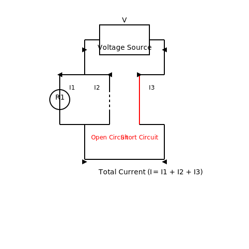
4.2 Testing Techniques for Parallel Circuits
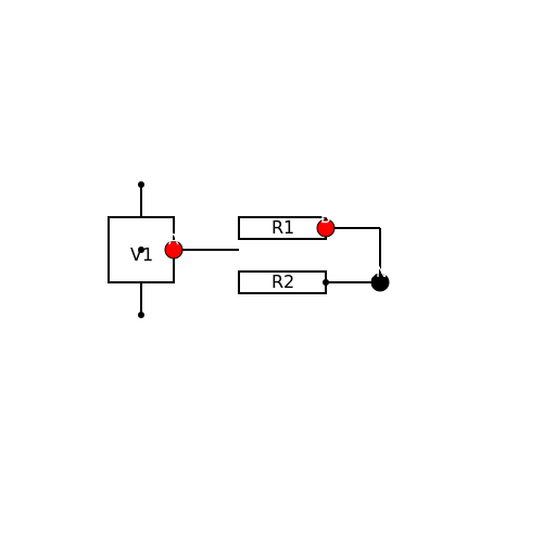
In the realm of DC parallel circuits, understanding appropriate testing techniques is crucial for verifying functionality, safety, and performance. The distinct characteristics of parallel circuits—where components share the same voltage—bring unique challenges that demand specific testing approaches. One basic yet effective technique is measuring voltage across components. Given that in a parallel circuit, all elements experience the same voltage, a simple voltmeter can be utilized. When testing, connect the voltmeter across the terminals of one of the load components, ensuring minimal disturbance to the circuit itself. This measurement allows you to confirm that the voltage supply is being effectively distributed. To stringently validate current distribution within each branch, you can apply an ammeter inline, effectively isolating each component serially. This technique is important because it helps identify potential issues like excessive current draw, which may lead to circuit damage. In a healthy circuit, the total current can be computed as the sum of individual branch currents, governed by Kirchhoff's Current Law, which states that the algebraic sum of currents entering a junction equals zero. For analytical purposes, let’s derive how individual branch currents can be computed. Given a simple parallel circuit with resistors \( R_1, R_2, \ldots, R_n \) connected across a voltage \( V \), each current can be expressed using Ohm's Law: $$ I_i = \frac{V}{R_i} $$ The total current \( I_{\text{total}} \) flowing from the power source can then be represented as: $$ I_{\text{total}} = I_1 + I_2 + \ldots + I_n $$ Substituting the individual currents, we yield: $$ I_{\text{total}} = \frac{V}{R_1} + \frac{V}{R_2} + \ldots + \frac{V}{R_n} $$ Factoring out the voltage \( V \): $$ I_{\text{total}} = V \left( \frac{1}{R_1} + \frac{1}{R_2} + \ldots + \frac{1}{R_n} \right) $$ This relationship emphasizes the parallel circuit's behavior—adding more branches decreases the overall resistance, thus increasing the total current from the source. When testing the complete circuit, it is prudent to utilize a power analyzer. This device not only assesses voltage and current but also calculates power factor, efficiency, and total harmonic distortion, essential for ensuring compliance with performance specifications in sensitive applications such as industrial machinery or renewable energy systems. It is also vital to conduct thermal imaging. By using an infrared camera, one can identify hotspots that may indicate poor connections or component failures, enhancing preventive maintenance strategies. Lastly, integrating digital multimeters (DMMs) with data logging capabilities permits comprehensive monitoring over time. Continuous monitoring can detect transient issues, contributing significantly to the reliability of systems in critical applications such as telecommunications and data centers. In summary, employing a combination of straightforward voltage measurements, detailed current analysis, comprehensive circuit assessments, and modern diagnostic tools enables optimized testing techniques for DC parallel circuits, leading to enhanced system reliability and performance. Understanding and implementing these techniques provides engineers and researchers a robust framework for operational validation and troubleshooting.References for Further Reading
- Electronics Tutorials - Parallel Circuits — This resource effectively explains the principles and analysis techniques of parallel circuits, laying a solid foundation for further exploration of testing methods.
- All About Circuits - Parallel Circuits — A detailed exploration of parallel circuits, including their characteristics, analysis, and practical applications, essential for electrical engineering students.
- Analog Devices - Understanding Resistor Parallel and Series — This article delves into the behavior of resistors in parallel and series configurations, providing clarity on current distribution and testing implications.
- Electronics Tutorials - Measuring Current and Voltage — A comprehensive guide on effective techniques for measuring voltage and current in circuits, specifically focusing on practical applications and methodologies.
- OMICRON - Applications in Substation Automation — This resource showcases the importance of testing techniques in ensuring the reliability of power systems, emphasizing methodologies applicable to parallel circuits.
- Fluke - Electrical Parameter Testing in Parallel Circuits — Insights on best practices for measuring electrical parameters in parallel configurations using professional measurement tools and techniques.
- ResearchGate - Application of Circuit Simulation Programs — A scholarly examination of circuit simulation tools in studying parallel circuit behaviors, essential for advanced research applications in circuit analysis.
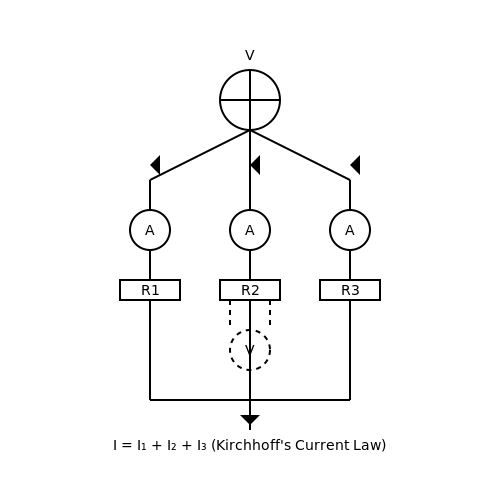
4.3 Steps for Troubleshooting and Repair
In the realm of DC parallel circuits, troubleshooting and repair require a systematic approach, considering both the electrical principles involved and the physical components. When faced with a malfunctioning circuit, whether in an embedded system or a larger power distribution context, engineers need to methodically identify the root cause of the issue.Understanding the Basics of the DC Parallel Circuit
Before diving into troubleshooting steps, it’s crucial to recall that in a DC parallel circuit, multiple components share the same voltage across their terminals and the total current is the sum of the currents through each component. If any branch of the circuit fails, the remaining branches continue to function, which often complicates the troubleshooting process. Some common issues that can arise include open circuits, short circuits, or component failures.Systematic Troubleshooting Steps
1. Visual Inspection Always start with a thorough visual inspection of the circuit. Look for any burnt components, disconnected wires, or signs of corrosion. Anomalies in solder joints or component orientation can lead to significant issues. Keep in mind that a simple external check can prevent further complications. 2. Isolate the Problem Determine which section of the circuit is malfunctioning. You can achieve this by selectively removing power to different branches or components, utilizing switches or disconnecting terminals. 3. Measure Voltages Using a multimeter, measure the voltage at various points within the circuit. Ensure that the voltage readings align with expected values. If a component is designed to receive 12V, for example, any significant deviation can indicate a fault. 4. Test Components Individually test components using the appropriate testing method. For resistors, use the ohmmeter function of a multimeter. For capacitors, a capacitance meter can accurately determine whether a capacitor is still within its specified values. For transistors, measure the current gain (hFE) using a transistor tester. 5. Check Connections and Wiring Continuity testing is essential in ensuring that there are no breaks in wiring or poor connections. If you suspect a disconnection, ensure to follow the wire's path, checking terminals and contact points with your multimeter set to continuity mode.Advanced Analysis Techniques
In more complex scenarios, incorporating simulation tools like SPICE can aid in visualizing circuit behaviors under different configurations. If the physical diagnostics do not yield a clear result, simulate the circuit to compare its expected vs. actual performance.Repair Strategies
Once the fault is identified, repairs can follow a prioritized approach: 1. Replace Faulty Components Whenever a damaged component is detected, replacing it with an equivalent one is essential. Ensure that the new components strictly meet the circuit specifications. 2. Re-solder Connections For weak joints or faulty solder connections, re-soldering ensures stable electrical continuity. A well-heated soldering iron can facilitate a secure joint. 3. Reroute or Shield Wiring if Necessary In cases where wire insulation is compromised or routing causes interference, consider rerouting or adding shielding to avoid future issues. By following these structured steps, engineers can diagnose and repair DC parallel circuits effectively, honing both practical skills and theoretical understanding. Additionally, keeping up with current techniques in circuit analysis and repair amplifies efficiency when faced with circuit integrity challenges.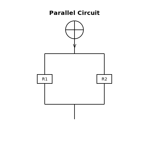
5. Recommended Textbooks and Articles
5.1 Recommended Textbooks and Articles
- Fundamentals of Electric Circuits by Charles K. Alexander and Matthew N.O. Sadiku — This textbook offers a comprehensive understanding of electric circuit concepts, including DC parallel circuits, with numerous examples, problems, and detailed explanations.
- The Art of Electronics by Paul Horowitz and Winfield Hill — Known for its practical approach to complex electronics, this book covers a wide array of topics including parallel circuits in DC applications, providing insights and useful anecdotes.
- All About Circuits: Direct Current Section — A freely accessible online textbook offering an exhaustive treatment of DC circuits including parallel configurations. It provides theoretical content complemented by interactive simulations.
- Principles for Current Division Calculations in Parallel Circuits by IEEE — This article delves into the mathematical principles behind current division in parallel DC circuits, perfect for engineers looking to deepen their understanding.
- Current in Parallel Resistor Networks — An easily digestible tutorial that explains the calculations required to analyze current paths through parallel resistors, enriched with diagrams and worked examples.
- Circuit Analysis For Dummies by John Santiago — Aimed at simplifying the understanding of circuit analysis, this book includes sections on solving parallel circuits with step-by-step guidance and practical tips.
- Introduction to Electric Circuits by Richard C. Dorf and James A. Svoboda — This book is ideal for both academic learning and as a reference; it covers a comprehensive range of topics, including DC parallel circuits.
- Basic Engineering Circuit Analysis by J. David Irwin — Detailed treatment of circuit analysis techniques, including parallel circuits, supported by modern examples and practical applications for professionals and students alike.
- Electronics for Embedded Systems by Ahmet Bindal — Focuses on practical electronics, this resource includes a look at DC circuits among other crucial topics, suitable for those pursuing engineering in the field of embedded systems.
5.2 Online Resources and Tutorials
- Khan Academy: Electrical Engineering — A comprehensive collection of lessons on electrical engineering concepts, including DC parallel circuits. This repository targets undergraduate and graduate students with interactive exercises.
- Electronics Tutorials — Offers detailed explanations of various electronic components and circuit types, including DC parallel circuits. Each topic includes theoretical knowledge and practical examples for better understanding.
- Coursera: Circuits and Electronics — This course, provided by MIT, covers fundamental concepts in electronics. It includes an exploration of DC circuit analysis, addressing both parallel and series circuits phenomena.
- TutorialsPoint: Electronic Circuits — An excellent resource for students and professionals, offering concise tutorials on DC circuits, among other topics. The platform also incorporates practical quiz sections to test the reader's knowledge.
- edX: Circuit Design — Through this course provided by Delft University of Technology, learners delve into the complexities of circuit design with a focus on both theoretical and practical aspects of parallel DC circuits.
- All About Circuits: Direct Current — This textbook resource extensively covers direct current principles, including specific lessons on parallel configurations. It's especially useful for professionals seeking in-depth explanations.
- YouTube: Electrical Circuits Playlist — A curated playlist featuring instructional videos on the fundamentals of electrical circuits, with sections dedicated to the analysis and practical applications of DC parallel circuits.
5.3 Professional Organizations and Journals
For those deeply engaged in the intricate world of DC parallel circuits, understanding the state-of-the-art developments and research trends is crucial. Professional organizations and journals play an indispensable role in disseminating cutting-edge findings, fostering collaboration, and setting industry standards. Below is a list of notable professional organizations and journals where you can find comprehensive resources dedicated to DC parallel circuits and related topics.- Institute of Electrical and Electronics Engineers (IEEE) — IEEE is one of the world’s largest technical professional organizations. They offer a wealth of resources, including journals, conferences, and standards that are critical for those researching DC circuits.
- IEEE Xplore Digital Library — This digital library provides access to IEEE journals, conferences, and standards, offering thousands of articles on electrical engineering subjects, including in-depth studies on DC parallel circuits.
- Springer Journals in Electronics and Electrical Engineering — Springer offers a variety of journals focusing on electronics and electrical engineering. It's a great resource for comprehensive studies in parallel circuits.
- Institute of Physics (IOP) Publications — IOP provides free and paid access to various physics and electronics journals. Their platform is rich with resources for the academic and professional community.
- SAGE Journals in Electronics and Electrical Engineering — SAGE offers a variety of peer-reviewed journals covering current and advanced research topics in electronics, with significant content related to DC circuits analysis.
- Association for Computing Machinery (ACM) — ACM is primarily known for computing, but many interdisciplinary papers are relevant to those researching interfaces between computational methods and electrical circuit design.
- MDPI Electronics Journal — This open-access journal publishes articles on the design and implementation of circuit systems, including innovations in DC parallel circuits.
- Taylor & Francis Online — Offers numerous journals and books on engineering disciplines, providing substantial research articles that can enhance the understanding of modern DC parallel circuits.