Brushless DC Motor Controllers
1. Working Principle of Brushless DC Motors
1.1 Working Principle of Brushless DC Motors
Brushless DC (BLDC) motors have emerged as a cornerstone in various applications, thanks to their high efficiency, reliability, and versatility. Unlike their brushed counterparts, which require mechanical commutation, BLDC motors utilize electronic controllers to achieve the required commutation. This section delves into the operational mechanisms of BLDC motors, exploring the fundamentals that render them unique and broadly applicable in modern technologies.
Fundamental Structure and Design
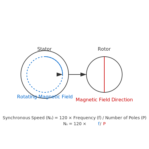
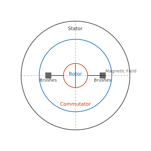
At the core of a brushless DC motor lies a combination of a stator and a rotor. The stator, typically composed of several windings, generates a rotating magnetic field when energized. Conversely, the rotor is made of permanent magnets and rotates within this magnetic field. This configuration minimizes the wear and tear associated with brushes and commutation, which significantly enhances the lifespan of the motor.
One of the primary distinctions of brushless motors is the control strategy employed. Commutation in brushless motors is achieved electronically through feedback mechanisms, rather than mechanically as in brushed motors. This not only improves performance but also provides opportunities for advanced control techniques such as vector control and direct torque control.
The Principle of Operation
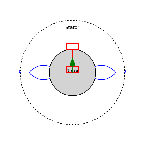
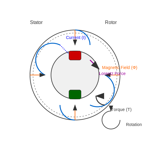
The operation of a brushless DC motor can be understood by analyzing the interaction between the rotating magnetic field of the stator and the magnetic field generated by the rotor. When the stator winding is energized, it creates a magnetic field that interacts with the rotor’s permanent magnets. The rotor is subjected to the Lorentz force, which causes it to rotate in the direction of the rotating magnetic field.
To mathematically describe the torque produced in a BLDC motor, we can use the following equation derived from the basic principles of electromagnetism:
In this equation:
- T is the torque produced by the motor,
- k is a constant that depends on the construction of the motor,
- \(\Phi\) is the magnetic flux produced by the rotor’s magnets, and
- I is the current flowing through the stator windings.
Electronic Commutation
A pivotal aspect of the brushless motor's operation is electronic commutation, which replaces the mechanical commutation found in brushed motors. The controller manages the supply of electric power to the stator windings in a sequence that aligns with the rotor's position. This synchronization is typically achieved via feedback from sensors such as Hall-effect sensors or encoders. These devices provide real-time information regarding the rotor's position, allowing for precise control over the motor’s operation.
The implementation of electronic commutation showcases advantages such as:
- Higher Efficiency: Reduced losses due to the absence of brush friction.
- Improved Control: Enhanced torque control and response times due to precise commutation.
- Lower Noise: Quieter operation, making them suitable for applications requiring low noise levels.
Real-World Applications
The applicability of brushless DC motors spans various fields, including:
- Electric Vehicles: Providing efficient propulsion systems.
- Aerospace: Utilized in servos and actuators due to their reliability.
- Consumer Electronics: Found in computer cooling fans and hard drives.
As technology advances, the integration of brushless DC motors continues to expand, affirming their critical role in the evolution of electric and automated systems. Understanding the operational principles behind these motors equips engineers and researchers to innovate further in applications where efficiency and performance are paramount.
1.2 Advantages Over Brushed DC Motors
In the realm of modern electromechanical systems, the brushless DC (BLDC) motor has emerged as a prominent choice for many applications, particularly as its advantages over traditional brushed DC motors become increasingly apparent. These advantages stem from fundamental differences in design, operation, and performance metrics.
The most significant advantage of brushless DC motors over their brushed counterparts lies in the absence of brushes, effectively eliminating the mechanical wear associated with brush contacts. This design feature not only enhances durability but also leads to a significantly increased lifespan. In addition, this absence allows for a greater range of operating speeds without the risk of overheating.
Enhanced Efficiency and Performance
Brushless motors generally operate at a higher efficiency compared to brushed motors, largely due to the elimination of brush friction and sparking. This characteristic translates to lower energy consumption and less thermal waste, making BLDC motors suitable for applications requiring prolonged operation or battery-powered devices. In contexts such as electric vehicles and renewable energy systems, where efficiency is paramount, BLDC motors exemplify superior performance.
Moreover, the controllability of brushless motors is advanced through the utilization of electronic controllers, which allows for precise adjustment of speed and torque. For instance, Pulse Width Modulation (PWM) techniques facilitate robust and efficient control, resulting in smoother performance and responsiveness that traditional brushed motors often struggle to match.
Improved Thermal Management
The design of BLDC motors contributes to enhanced thermal management. The motor windings are located on the stator rather than the rotor, which allows for better heat dissipation. In contrast, brushed motors exhibit localized heating due to brush contact points, which can lead to premature failure. The efficient thermal management in BLDC motors, combined with higher operational speeds, results in a lower risk of overheating, further contributing to reliability in demanding environments.
No Electrical Noise
An additional benefit is the reduction of electrical noise and electromagnetic interference. The absence of brush contact means that BLDC motors generate far less electromagnetic noise, making them preferable in applications sensitive to interference, such as audio equipment and medical devices. This characteristic underlines their suitability for diverse sectors where performance integrity is critical.
Compact and Lightweight Design
Brushless motors are often more compact than their brushed counterparts, owing to their simpler construction and the absence of mechanical commutation components. This compactness is particularly advantageous in applications where space constraints are critical, such as drones and robotics. The lightweight nature of BLDC motors also facilitates increased mobility and efficiency in portable devices.
In summary, while both brushed and brushless DC motors have their unique advantages, it is clear that BLDC motors provide substantial benefits in terms of efficiency, lifespan, thermal performance, noise levels, and compactness. These advantages make them an ideal choice for a wide range of applications, paving the way for continued innovation in electric motor technology.
1.3 Applications of Brushless DC Motors
Brushless DC motors (BLDC) are the preferred choice in various high-performance applications due to their efficiency, reliability, and precise control capabilities. Unlike traditional brushed motors, the absence of brushes in BLDC motors eliminates friction and wear, enhancing their lifespan and performance. This section will delve into their wide-ranging applications, exploring how their unique characteristics contribute to advancements across different sectors.
Industrial Automation
In industrial automation, BLDC motors are integral for applications requiring precise speed and position control. Their ability to maintain constant torque over a wide range of speeds makes them ideal for automated assembly lines, robotics, and conveyor systems. Additionally, many industrial robots utilize BLDC motors for joint actuators due to their high power-to-weight ratio and responsiveness.
Aerospace and Aviation
The aerospace sector leverages BLDC motors in applications where reliability and lightweight components are critical. These motors are commonly found in unmanned aerial vehicles (UAVs), flight control systems, and actuator mechanisms. Their high efficiency contributes not only to longer flight times but also to the overall reduction in system weight, crucial for fuel efficiency and performance.
Consumer Electronics
In consumer electronics, the demand for compact and efficient devices has pushed the adoption of BLDC motors in applications such as computer cooling fans, hard disk drives, and small appliances. Their silent operation and reduced electromagnetic interference make them suitable for consumer products that require minimal noise and optimal performance while conserving energy.
Electric Vehicles
The automotive industry has significantly benefitted from the integration of BLDC motors in electric and hybrid vehicles. These motors serve as the main propulsion source due to their high efficiency and reliability, providing smoother acceleration and regenerative braking capabilities. Moreover, they contribute to extended battery life, critical for optimizing range and overall vehicle performance in electric cars.
Medical Devices
BLDC motors play a vital role in the medical field, powering devices such as MRI machines, surgical robots, and portable medical equipment. Their ability to provide precise control and high reliability ensures accurate measurements and effective operation, which are essential in medical diagnostics and treatment.
HVAC Systems
In heating, ventilation, and air conditioning (HVAC) systems, BLDC motors are used in blowers and fans. The energy efficiency of these motors translates to lower operational costs and reduced energy consumption. Their advanced control algorithms can adapt to varying load requirements, thus optimizing performance and enhancing user comfort.
The increasing adoption of brushless DC motors across diverse sectors reflects their pioneering role in modern technology. As industries evolve and demand greater efficiency and performance, the capabilities offered by BLDC motors continue to expand, paving the way for innovative applications that were previously thought unattainable.
2. Overview of Motor Control Techniques
2.1 Overview of Motor Control Techniques
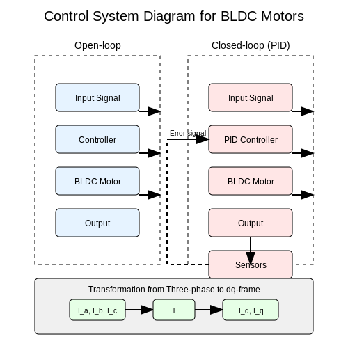
Brushless DC (BLDC) motor controllers represent a cornerstone of modern electromechanical systems, leveraging multiple motor control techniques to achieve optimal performance. Understanding these techniques is essential for engineers and researchers striving to design efficient and responsive systems. Initially, let's explore the fundamental control strategies employed in BLDC motors, namely open-loop and closed-loop control systems.
Open-Loop Control Systems
In an open-loop control system, the controller operates without feedback from the output. This simplicity makes open-loop systems less complicated, and they are often used in applications where the setpoint does not vary significantly. The primary advantage resides in their low cost and ease of implementation. However, a notable drawback of open-loop systems is their vulnerability to disturbances and variations in load.
For instance, a basic pulse-width modulation (PWM) signal can drive a BLDC motor in an open-loop fashion. The signal's duty cycle determines the motor's speed, while the lack of feedback means any changes in load or environmental conditions are unaccounted for, potentially leading to inefficient operation.
Closed-Loop Control Systems
In contrast, closed-loop control systems utilize feedback to regulate performance. This involves continuously monitoring the motor's output—such as speed or position—and adjusting the input accordingly. By employing sensors (like encoders or hall effect sensors) to provide real-time feedback, closed-loop systems can enhance precision and efficiency.
One common closed-loop technique is proportional-integral-derivative (PID) control, which combines three methodologies:
- Proportional Control (P): This adjusts the control output proportionally to the error signal (the difference between the desired and measured output).
- Integral Control (I): This component accumulates past errors, helping eliminate steady-state errors that proportional control alone may not suffice.
- Derivative Control (D): This predicts future error based on its rate of change, effectively dampening oscillations and improving system stability.
Mathematically, the PID controller can be expressed as:
Where u(t) is the control output, e(t) is the error signal, and Kp, Ki, and Kd are the proportional, integral, and derivative gains, respectively. Effective tuning of these gains is critical to the performance of the PID controller, influencing responsiveness, stability, and steady-state error.
Vector Control and Field-Oriented Control
In more advanced applications, especially those requiring high-performance control of brushless motors, techniques like vector control or field-oriented control (FOC) enhance the responsiveness and efficiency of drive systems. The core principle behind these techniques lies in decoupling the torque and flux control of the motor, allowing independent management of these two critical aspects.
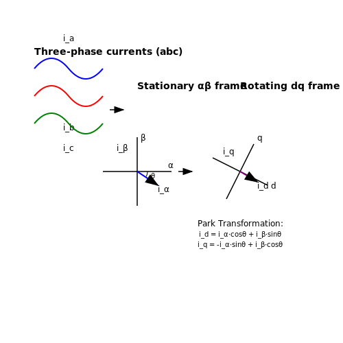
Vector control operates in a coordinate system that aligns with the rotating magnetic field of the motor. This transformation allows for a more direct and effective action over torque production and speed control, leading to smooth operation across a wide range of speeds. The mathematical representation here is based on transforming the three-phase current measurements into a two-axis format commonly known as the dq-frame.
Where Id and Iq are the direct and quadrature currents, and T is the transformation matrix. This approach is prevalent in applications requiring high dynamics, such as electric vehicles and robotics, where precise control significantly impacts performance and efficiency.
Lastly, understanding these motor control techniques equips engineers and researchers with the vital knowledge necessary to tailor solutions that optimize motor performance for various applications, from consumer electronics to industrial automation and beyond.
2.2 Types of Brushless DC Motor Controllers
Brushless DC (BLDC) motor controllers play a crucial role in the operation and efficiency of brushless motors. Understanding the different types can illuminate their applications across various industries, allowing engineers and researchers to select the most suitable controller for their specific needs. Essentially, BLDC motor controllers can be categorized into several types based on their configuration and control methodologies.
Types Based on Control Methods
The primary distinction among BLDC motor controllers arises from the control method employed to manage motor operation. These methods are fundamentally designed to manage the voltage and current supplied to the motor, subsequently affecting its speed and torque.
1. Trapezoidal Control
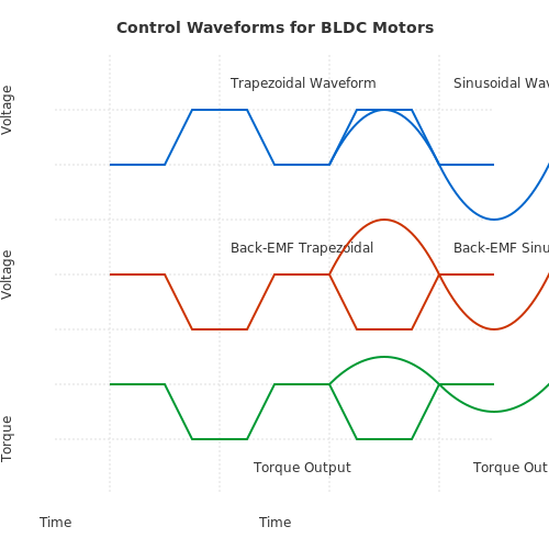
Trapezoidal control is one of the simplest and most common control strategies used in BLDC motor applications. This method operates on the principle of controlling the motor phases sequentially in a trapezoidal waveform, which corresponds to the back electromotive force (back-EMF) generated by the motor. A trapezoidal current waveform allows for easier commutation, simplifying the controller hardware.
Advantages: This method is particularly advantageous in applications where cost is a concern as it requires less complex circuitry. Moreover, trapezoidal control is efficient at low speeds and is suitable for applications such as fans and small pumps.
2. Sinusoidal Control
In contrast, sinusoidal control provides a smoother performance by producing a sinusoidal waveform for the current. This is achieved by employing algorithms that accurately align the phase commutation with the back-EMF sinusoid of the motor. The sinusoidal method often results in reduced cogging torque, leading to quieter operation and improved overall efficiency.
Applications: This approach is particularly effective in high-performance applications requiring precise control, such as electric vehicles and robotics.
Types Based on Feedback Mechanisms
Another axis of classification for BLDC motor controllers pertains to their feedback mechanisms, which provide real-time data about the motor's operational state. The choice of feedback mechanism profoundly affects the responsiveness and accuracy of the control strategy.
1. Open-Loop Control
Open-loop control systems operate without feedback regarding the actual motor position or performance metrics. Instead, they rely on pre-set parameters, such as voltage and current limits, to drive the motor. While open-loop systems are simpler and more cost-effective, they lack adaptability to varying load conditions or dynamic environments.
Limitations: This controller type is generally more suitable for applications with predictable loads, such as in low-cost DC fans.
2. Closed-Loop Control
Closed-loop control systems utilize feedback from sensors to optimize performance continually. Sensors such as Hall effect sensors or rotary encoders measure the motor’s position, speed, or current and provide this data back to the controller. Feedback allows for real-time adjustments, improving performance across varying loads and enhancing efficiency.
Use Cases: Closed-loop systems are preferred in precision applications, such as CNC machines and robotics, where maintaining accuracy is paramount.
Type Based on Power Electronics
The configuration of power electronics within the motor controller also influences performance characteristics. Two prevalent types include:
1. Integrated (IC-Based) Controllers
IC-based controllers combine various functionalities into a single chip, offering a compact solution. These integrated circuits (ICs) facilitate ease of use and integration into complex systems, often including built-in protections against over-current, overheating, and voltage spikes.
2. Discrete Component Controllers
In contrast, discrete controllers involve various individual components for each function within the control system. While generally larger and more complex, they allow for greater customization and flexibility, which can be advantageous in specialized applications.
Conclusion and Practical Relevance
The choice of a brushless DC motor controller greatly influences performance, efficiency, and application suitability. As the demand for precise and efficient motor control escalates in various sectors, understanding the nuances of these controllers is imperative. By evaluating the control method, feedback mechanism, and electronic configuration, engineers can design better systems that meet the high standards of today’s technological landscape.
2.3 Key Components of a Motor Controller
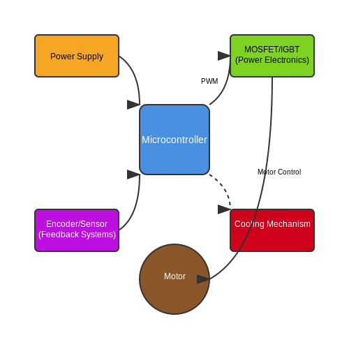
Brushless DC (BLDC) motor controllers play a vital role in the effective operation of brushless motors, enabling precise control over speed, torque, and positioning. Understanding the key components of a motor controller is essential for engineers and researchers working in fields such as robotics, automotive systems, and industrial automation. The architecture of a typical BLDC motor controller may consist of several fundamental elements, each contributing to the overall performance. In this section, we will take a deeper look at these critical components.
Power Supply and Voltage Regulation
At the heart of any motor controller is the power supply, which must provide the necessary voltage and current to drive the motor effectively. Power supplies for BLDC controllers typically convert AC mains voltage to a regulated DC voltage suitable for the motor.
Voltage regulation is particularly important, as fluctuations can cause performance issues or even damage the motor. Linear voltage regulators or switching regulators are commonly employed to maintain consistent voltage levels. For example, a switching regulator is often favored in high-power applications due to its efficiency and ability to handle larger loads while minimizing heat dissipation.
Microcontroller and Firmware
The microcontroller serves as the brain of the motor controller. It executes the firmware that dictates the control algorithms necessary for motor operation. These algorithms can include speed regulation (such as PID control), commutation strategies, and fault detection routines. Field-Oriented Control (FOC) is an advanced technique often implemented in high-performance applications, offering smoother operation and enhanced efficiency by controlling the motor’s magnetic field directly.
Microcontrollers are selected based on various parameters such as computational speed, integrated peripherals, and memory. Enhanced features like PWM generation and ADC (Analog-to-Digital Converters) for feedback can provide significant advantages. For instance, a microcontroller with built-in PWM can directly modulate the voltage applied to the motor, achieving more precise control over speed and torque.
Power Electronics
Efficient control of motor power is governed by a selection of power electronic components, primarily MOSFETs (Metal-Oxide-Semiconductor Field-Effect Transistors) or IGBTs (Insulated Gate Bipolar Transistors). These components act as electronic switches, rapidly toggling the power supplied to the motor coils based on commands from the microcontroller.
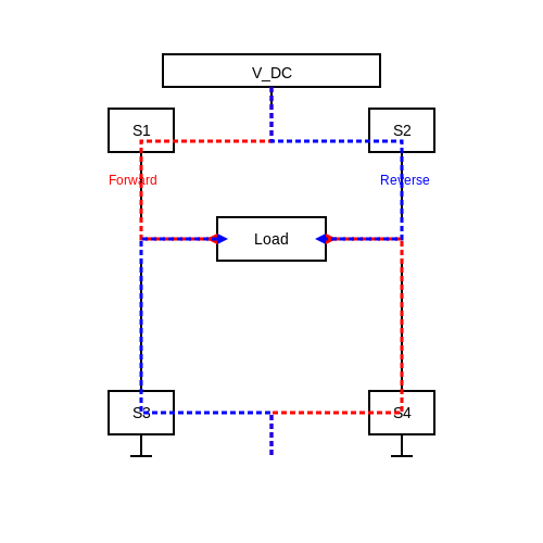
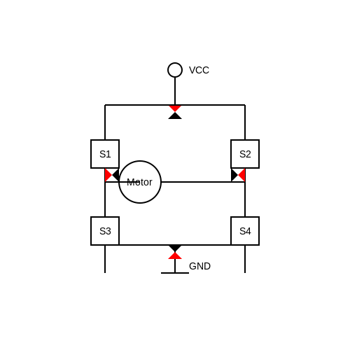
The design of the power stage often involves configuring these electronic switches in a H-bridge configuration for enabling bidirectional control of the motor. The H-bridge allows the controller to change the polarity of the voltage applied to the motor, facilitating both forward and reverse rotation. An optimized gate driver circuit is essential for ensuring rapid switching and efficient power conversion.
Feedback Systems
While the microcontroller governs the command signals, a reliable feedback system is crucial for performance monitoring and control. Common feedback mechanisms involve encoders or Hall effect sensors that provide position and speed information. This data enables the controller to make real-time adjustments to maintain desired performance levels.
For instance, an optical encoder can deliver precise rotational position data, allowing for accurate commutation and enhanced control over the motor's operation. The integration of feedback systems is particularly important in applications requiring high precision, as it directly impacts the responsiveness and stability of the motor controller.
Cooling System
An often-overlooked aspect of BLDC motor controllers is the cooling system. Since power electronic components can generate significant heat during operation, effective thermal management is necessary to maintain reliability and performance. Cooling methods range from passive heat sinks to more active solutions such as fans or liquid cooling systems.
Implementing efficient cooling reduces the risk of thermal shutdown and prolongs the lifespan of the power electronic components. The design should ensure that the operational environment is monitored, possibly integrating thermal sensors into the control algorithms to adjust power levels based on temperature readings.
In conclusion, each of these components—power supply, microcontroller, power electronics, feedback systems, and cooling mechanisms—work collaboratively to create a robust and efficient brushless DC motor controller. Achievements in this confluence of technology not only enhance the performance of BLDC motors but also expand their applicability in emerging fields such as electric vehicles, automated manufacturing, and renewable energy systems.
3. Hall Effect Sensor-based Control
3.1 Hall Effect Sensor-based Control
Brushless DC (BLDC) motors are becoming increasingly prevalent in various applications, from consumer electronics to aerospace engineering, owing to their efficiency, reliability, and wide range of operable speeds. Central to the effective operation of these motors is the control system, which directs the electronic commutation of the motor's phases. One popular method of achieving this control in BLDC motors is through Hall Effect sensors. The integration of Hall Effect sensors in BLDC motor controllers allows for precise rotor position sensing, facilitating optimized operation and performance.
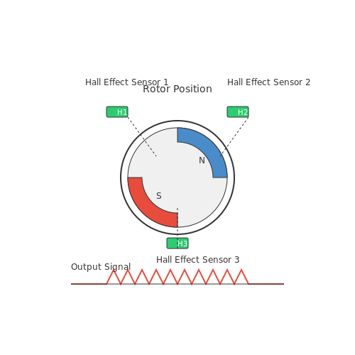
At the core of Hall Effect sensor-based control is the principle of the Hall Effect itself, which describes the phenomenon where a voltage (the Hall voltage) develops across a conductor when it is placed in a magnetic field. This voltage is proportional to the magnetic field strength and the current flowing through the conductor. In the context of BLDC motors, Hall Effect sensors are strategically placed to detect the position of the rotor and generate output signals that correspond to its orientation.
Working Principle of Hall Effect Sensors
When a Hall Effect sensor is placed close to a rotor magnet, it generates an output voltage that changes as the rotor spins. Typically, a BLDC motor may use three Hall Effect sensors spaced 120 degrees apart to cover a full 360-degree range of motion. As the rotor turns, each sensor sequentially activates as it aligns with the magnetic field of the rotor's permanent magnets. This enables the controller to determine the precise position of the rotor at any given moment.
The signals emitted by the Hall Effect sensors are converted into digital signals that the controller can interpret. This data is then utilized to switch the appropriate phase windings on and off, thus creating a rotating magnetic field that interacts with the rotor, prompting it to spin. The precise timing of these electronic switches directly impacts the motor's efficiency and torque production.
Mathematical Considerations
In the analysis and design of Hall Effect sensor-based motor controllers, several mathematical models are employed. A fundamental equation that describes the relationship between the electrical inputs and the resultant torque (τ) produced by the motor can be expressed as:
Here, \(k\) is a constant specific to the motor, \(I\) refers to the current flowing through the motor, and \(I_{th}\) is the threshold current needed to overcome the stator resistance. The control of this current directly influences the performance of the motor, as well as the efficiency of the Hall Effect sensors in providing accurate feedback.
Implementation and Practical Relevance
The implementation of Hall Effect sensor-based control systems extends beyond simple positional feedback. The advantages of this method are evident in applications where precision is paramount. For example, in robotics, drones, and electric vehicles, the ability to rapidly and accurately control the rotor ensures enhanced maneuverability and energy efficiency. Moreover, failures in Hall Effect sensors can be detected through redundancy, allowing for safe operation even in critical applications.
As you continue your exploration of brushless DC motor controllers, understanding the pivotal role of Hall Effect sensors and their mathematical underpinnings will equip you with the tools needed to optimize motor performance in your specific domain.
3.2 Sensorless Control Techniques
The development of brushless DC motors (BLDC) has transformed many applications, from electric vehicles to robotics. One significant advancement in the control of these motors is the implementation of sensorless control techniques. These methods eliminate the need for external position sensors, which can simplify system design, reduce cost, and enhance reliability.
Understanding Sensorless Control
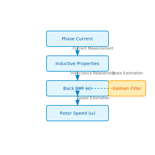
Sensorless control algorithms utilize various electrical characteristics of the motor to estimate rotor position and speed. This approach relies on the model of the motor dynamics and the feedback extracted from the motor's winding currents or voltages. Typically, sensorless control strategies exploit techniques such as back electromotive force (back EMF) detection, observer methods, and the use of the motor's inductive properties.
Back EMF Estimation
One of the most common techniques for sensorless control is back EMF estimation. The principle relies on the fact that the back EMF voltage is proportional to the rotor speed. By monitoring the back EMF voltage during operation, the controller can ascertain the rotor’s position. The back EMF for a phase in a BLDC motor can be expressed as:
where:
- e = back EMF voltage
- K_e = back EMF constant
- ω = angular speed of the rotor
The challenge lies in accurately measuring the back EMF when the motor is in motion, especially at low speeds where it can be comparatively small. Advanced filtering techniques are often employed to mitigate noise and enhance the estimation accuracy.
Model-Based Observer Techniques
Model-based observers, such as the Kalman filter, can also be used to estimate rotor position and speed. These techniques rely on mathematical models of the motor and system dynamics to optimally combine various measurements and predictions to estimate the motor states. The Kalman filter is particularly powerful because it can iteratively update the estimates based on new measurements, which provides robust performance even in the presence of noise.
Inductive Property Utilization
Another innovative approach involves using the inductive properties of the motor. By analyzing the relationship between phase current, voltage, and inductance, additional information can be extracted to infer rotor position. As the rotor moves, the inductance in the motor's phases changes, which can be mapped to obtain precise angle estimates.
Real-World Applications
Sensorless control techniques are widely utilized in applications where cost, reliability, and compactness are crucial. For instance, they are prevalent in:
- Electric bicycles
- Robotic arms and drones
- Automotive applications, such as electric vehicles
- Home appliance motors
The absence of sensors reduces complexity and potential points of failure, making sensorless systems an attractive option for many modern applications.
As technology advances and control algorithms become more sophisticated, the performance and reliability of sensorless control in brushless DC motors continue to improve, paving the way for even broader applications in the future.
3.3 Field-Oriented Control (FOC) Method
In the realm of brushless DC motors, the Field-Oriented Control (FOC) method stands out due to its advanced capabilities for efficient motor management. Unlike traditional speed control techniques, which often focus on just the magnitude of the input signals, FOC allows for sophisticated manipulation of both torque and flux components of the motor. This methodology can lead to enhanced performance in terms of responsiveness and smoothness in control. At its core, FOC operates by leveraging a dual coordinate transformation strategy. The essence of this approach is to decouple the torque (τ) and flux (φ) control, allowing them to be regulated independently. This decoupling fundamentally rests on transforming the three-phase motor currents from the stationary reference frame (the direct/quadrature, or dq-frame) to a synchronous rotating reference frame, thus simplifying the control calculations. To dive into the mathematics, it is essential to outline the transformations involved. First, we can express the three-phase currents \( i_a, i_b, i_c \) as follows: $$ i_{abc} = \begin{bmatrix} i_a \\ i_b \\ i_c \end{bmatrix} $$ Using Park's transformation, the currents can be transformed from the abc frame to the dq frame: $$ i_d = \frac{2}{3} (i_a \cos(\theta) + i_b \cos(\theta - \frac{2\pi}{3}) + i_c \cos(\theta + \frac{2\pi}{3})) $$ $$ i_q = \frac{2}{3} (i_a \sin(\theta) + i_b \sin(\theta - \frac{2\pi}{3}) + i_c \sin(\theta + \frac{2\pi}{3})) $$ Here, \( θ \) represents the rotor position angle, which is critical for correct transformation. Once transformed, the controller can independently regulate the torque-producing current \( i_q \) and the magnetizing current \( i_d \) based on the desired torque output and flux linkage, respectively. For instance, the torque \( τ \) produced by a brushed DC motor is related to the motor's back-emf and the currents: $$ τ = \frac{3}{2} \frac{P}{2} (i_d \cdot \phi_m + i_q \cdot \phi_f) $$ where \( P \) is the number of pole pairs, \( φ_m \) is the magnetic flux due to the rotor, and \( φ_f \) represents the flux produced by the stator. The feedback loop integral to FOC typically employs a proportional-integral (PI) controller to adjust the dq current references, ensuring minimal tracking errors while maximizing system stability. The choice of control gains is pivotal; they must be tuned to achieve a trade-off between responsiveness and overshoot, often requiring specialized tuning techniques like the Ziegler-Nichols method or the Cohen-Coon method in practical implementations. In practical applications, FOC has been employed in various high-performance settings, from electric vehicles to industrial automation systems, owing to its capacity to adapt quickly to changing loads and maintain efficiency across a wide range of operational conditions. Notably, FOC not only enhances torque production and minimizes ripple under load but also allows for quieter operation of BLDC motors, an essential aspect in consumer electronics. As we navigate deeper into FOC's implications in brushless motor control, it's crucial to recognize its importance in the landscape of modern electrical engineering. The challenges associated with implementing FOC, such as requiring a precise rotor position sensor or the complexity of the control algorithm, must be carefully balanced against its performance benefits in real-world applications, making it a significant focus area for continued innovation.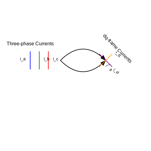
4. Power Requirements and Efficiency
4.1 Power Requirements and Efficiency
Brushless DC motors (BLDC) have garnered widespread application in various fields, including automotive, aerospace, and robotics, primarily due to their efficiency and performance. A critical factor that influences their operational effectiveness is the power requirements and efficiency of the associated motor controllers. Understanding these factors is essential for selecting the appropriate motor controller and for optimizing system performance.
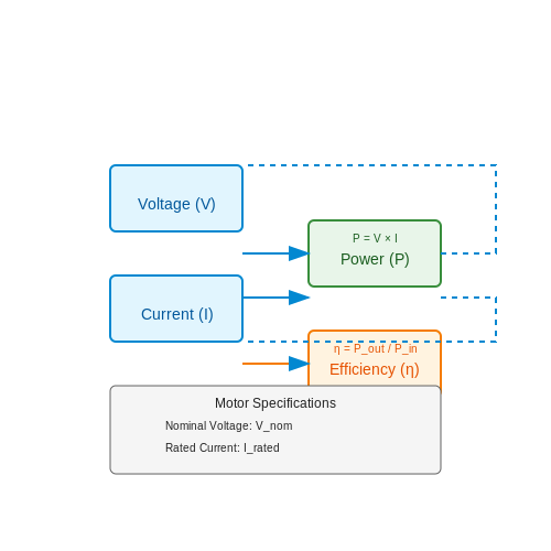
At the heart of a BLDC motor controller lies the challenge of converting electrical energy into mechanical energy efficiently. This conversion depends significantly on the balance between voltage, current, and resistance within the motor system. The power delivered to the motor can be quantified using the equation:
where P is the power in watts, V is the voltage in volts, and I is the current in amperes. To ensure optimal functioning, the controller must supply the required voltage and current while taking into account the motor's resistance.
Understanding Motor Specifications
Before delving into efficiency calculations, it is crucial to understand the specifications of the BLDC motor in use, particularly its voltage and current ratings. These specifications guide the design of the controller circuitry, including the choice of power MOSFETs or IGBTs used for switching. Typically, BLDC motors are rated based on:
- Nominal Voltage: The voltage for which the motor is designed to operate efficiently.
- Rated Current: The maximum continuous current the motor can handle without overheating.
- Peak Torque: The maximum torque the motor can produce under specific conditions.
- Efficiency Rating: Typically provided by the manufacturer, this indicates how well the motor converts electrical energy to mechanical power.
Efficiency of the Controller
The efficiency of the motor controller itself is another crucial aspect to consider. The controller's efficiency can be defined as:
where η is the efficiency, Pout is the output power delivered to the motor, and Pin is the power consumed by the controller from the power supply.
In most high-performance BLDC motor controllers, operational losses arise from switching losses in the MOSFETs (due to the finite rise and fall times of the gate drive signals), conduction losses (which are predominantly resistive losses due to the current flow through the transistors), and losses associated with the feedback mechanisms used to regulate motor speed and position. To maximize efficiency, engineers must carefully design the control algorithms and choice of power components.
Practical Relevance
The implications of power requirements and efficiency extend well beyond theoretical discussions. In real-world applications, optimizing these parameters directly influences system performance, thermal management, and the overall durability of the motor system. For example:
- Aerospace Applications: In UAVs, where weight and battery life are paramount, maximizing motor efficiency can lead to significantly extended flight times.
- Electric Vehicles: The efficiency of BLDC motors directly affects the driving range, making it crucial to use advanced controllers with high efficiency.
- Industrial Automation: In automated systems, efficient motors lead to lower operational costs and reduced heat generation, thus prolonging component life.
In summary, understanding the power requirements and efficiency of brushless DC motor controllers is essential for anyone involved in motor control applications. It not only enhances performance but also contributes positively to the longevity and reliability of the systems in which these motors operate.
4.2 Heat Management in Controllers
Heat management is a critical aspect of brushless DC motor controllers, significantly impacting both performance and longevity. As these controllers are commonly used in demanding applications—such as electric vehicles, robotics, and aerospace systems—it is essential to ensure they operate within optimal thermal limits. Effective heat management enhances efficiency and reliability, thus safeguarding both the controller components and the motor itself. One of the main sources of heat in brushless DC motor controllers is switching losses during the on-off transition of the semiconductor devices, primarily MOSFETs or IGBTs. These losses are influenced by the switching frequency, voltage, and load current. When the controller operates at high frequencies to achieve faster response times, these losses can become pronounced. Additionally, resistive losses in the current path add to the thermal burden, typically following the formula: $$ P_{loss} = I^2 R_{ds(on)} $$ where \(P_{loss}\) is the power loss, \(I\) is the current flowing through the device, and \(R_{ds(on)}\) is the on-state drain-source resistance.Thermal Management Strategies
To mitigate these losses, several thermal management strategies can be employed:- Heat Sinks: These passive devices dissipate heat generated by the controller into the environment. The efficiency of a heat sink depends on its thermal conductivity, surface area, and the airflow around it. When designing a heat sink, the following relationship is key:
$$ Q = hA(T_{s} - T_{a}) $$where \(Q\) is the heat dissipated, \(h\) is the heat transfer coefficient, \(A\) is the surface area, \(T_{s}\) is the surface temperature of the heat sink, and \(T_{a}\) is the ambient temperature.
- Active Cooling: In scenarios requiring greater heat dissipation, such as high-performance systems, active cooling methods like fans or liquid cooling may be employed. These methods can significantly enhance heat transfer, effectively lowering the thermal resistance.
- Thermal Interface Materials (TIMs): The use of TIMs between semiconductor devices and heat sinks is crucial for improving thermal contact. The thermal impedance of the interface affects the overall thermal resistance. Thus, careful selection of TIM can lead to better heat transfer.
- Temperature Sensing and Feedback: Integrating temperature sensors into the controller can allow for dynamic adjustments to the operating conditions. If the temperatures exceed predefined thresholds, the controller can reduce duty cycles or switch to a safer operational mode, thereby preventing overheating.
Real-world Applications
In high-performance applications such as aerospace, maintaining optimal thermal conditions is non-negotiable. For example, modern drones often employ brushless DC motors with advanced controllers that utilize a combination of heat sinks and active cooling to operate under stringent thermal constraints without performance degradation. Similarly, in electric vehicles, engineers employ sophisticated thermal management systems to ensure battery-powered brushless motors maintain high efficiency during acceleration and deceleration.Conclusion
In summary, understanding heat management in brushless DC motor controllers is paramount for enhancing their performance and longevity. With the strategic implementation of thermal management techniques, such as heat sinks, active cooling, and effective thermal interface materials, engineers can ensure reliable operation under various operational conditions. As technologies advance and applications become more demanding, continuing innovation in heat management will remain a critical focus in the design and implementation of these systems.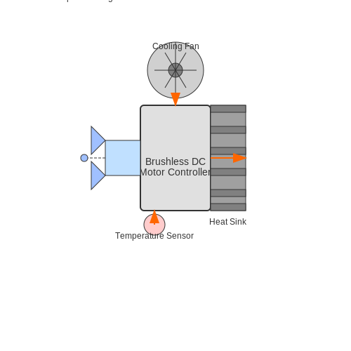
4.3 PCB Design Considerations
When designing a printed circuit board (PCB) for brushless DC (BLDC) motor controllers, various factors must be considered to optimize performance, reliability, and compactness. This section delves into the nuances of PCB layout specific to driving BLDC motors, emphasizing the interplay between electrical characteristics, thermal management, and electromagnetic interference (EMI).Power Path Optimization
One of the primary considerations in PCB design is managing the power path effectively. The traces that carry current to the motor must be sized appropriately to prevent excessive voltage drops and ensure minimal power losses. For high-current applications, using wider traces or multiple layers can facilitate thermal dissipation and enhance reliability. The relationship governing resistance in a conductive medium is captured by the equation:Thermal Management
Thermal considerations are crucial, particularly because brushless DC motors can draw significant currents, leading to heat generation in various components, including MOSFETs and resistors. Heat sinks or thermal vias can be employed to dissipate heat effectively. Proper heat management techniques not only prolong component lifespan but also enhance overall system reliability. A simplified thermal resistance formula can be utilized as a guide:EMI and Noise Reduction Techniques
EMI poses a notable challenge in BLDC motor controllers. The rapid switching actions inherent to the motor-driving circuits can generate significant noise. To mitigate this, employing proper grounding techniques, such as a star ground configuration, can minimize ground loops and EMI coupling. Additionally, using decoupling capacitors close to the power pins of ICs can help stabilize voltages and absorb high-frequency noise. The placement of these components should be based on minimizing return paths for high-frequency signals, which can typically be modeled by:Layout Considerations
Efficient usage of PCB space contributes to both mechanical stability and electrical performance. Placing components in a manner that keeps high-frequency and high-current paths short minimizes inductance and resistance. Using multiple ground and power planes can also reduce noise, ensuring robust performance. Furthermore, incorporating design rules for distance between traces can help prevent interference. As a rule of thumb, maintaining a separation of at least three times the trace width can mitigate crosstalk between adjacent signal lines.Case Studies and Practical Implementations
Real-world implementations of BLDC motor controllers benefit significantly from these design considerations. For instance, in the robotics industry, optimized PCBs frequently result in enhanced motor performance, achieving greater torque and smoother operation while reducing the risk of overheating and failure. One illustrative example is the PCB design used in drone controllers. These systems rely on efficient brushless motors, where design decisions directly impact flight stability and responsiveness. In conclusion, PCB design for brushless DC motor controllers involves a holistic approach that integrates electrical, thermal, and mechanical considerations. Each aspect harmonizes to enhance performance and reliability, illustrating the complexity and artistry that underpins the engineering of these systems.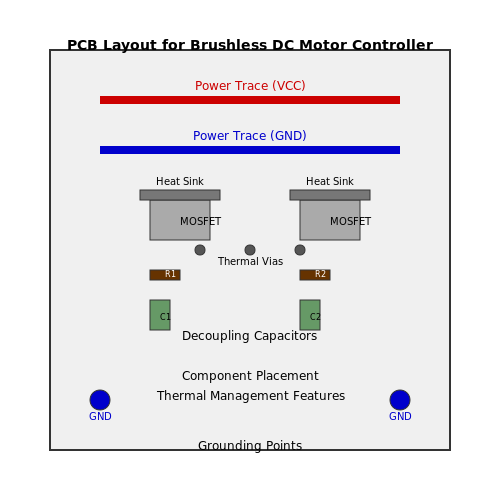
5. Integration with Microcontrollers
5.1 Integration with Microcontrollers
Understanding Brushless DC Motor Controllers
The integration of brushless DC (BLDC) motor controllers with microcontrollers represents a significant evolution in the control of electric motors. This convergence allows for precise control of motor functions, thereby increasing efficiency and operational performance in various applications, from robotics to electric vehicles. At the heart of a BLDC motor controller lies the electronic commutation process, which replaces traditional mechanical brushes with electronic circuits, enabling a more reliable and efficient operation. This improvement can be attributed to advancements in semiconductor technology, which facilitate the development of compact and efficient driver circuits capable of interfacing seamlessly with microcontrollers.Microcontroller Selection Criteria
When selecting a microcontroller for your BLDC motor controller, several criteria must guide your decision:- Processing Power: The microcontroller should have adequate processing capabilities to manage control algorithms in real-time, which often include pulse-width modulation (PWM) for speed control.
- I/O Interfaces: Depending on the complexity of your setup, you may need PWM outputs, ADC inputs for feedback signals, and communication interfaces like SPI or I2C.
- Integration Level: Choose a microcontroller that integrates necessary peripherals to minimize PCB space and increase reliability.
- Programming Environment: Select a microcontroller that fits well within your development ecosystem and programming preferences.
Control Algorithms and Implementation
The implementation of control algorithms in BLDC motor controllers typically involves several stages, from sensor integration to control loop execution. Common algorithms used include: Field-Oriented Control (FOC): Also known as vector control, FOC is crucial for achieving high performance in terms of responsiveness and efficiency. It requires measuring rotor position using encoders or Hall sensors, allowing the controller to optimize current flows in the motor coils. To implement FOC, we often deal with the transformation of the three-phase currents into a two-dimensional rotating reference frame. The transformation can be elegantly expressed using the following equations:Pulse Width Modulation (PWM)
PWM is essential for controlling the voltage supplied to the motor, effectively managing its speed and direction. The principle of PWM involves varying the duty cycle of a digital signal, effectively controlling the average voltage and current flowing to the motor. The relationship between PWM duty cycle \(D\), voltage \(V_{supply}\), and effective voltage \(V_{output}\) across the motor can be defined as follows:Real-World Applications
In practice, microcontroller-integrated BLDC motor controllers are ubiquitous. They are found in electric bicycles, drones, and robotics, where precise motion control is paramount. Engineers continually refine these systems to enhance their efficiency and responsiveness, utilizing various feedback mechanisms to adapt to operational demands. Integrating BLDC motor controllers with microcontrollers enhances their capability dramatically, allowing for the fine-tuning of motor responses essential for various applications in advanced engineering systems. As technology progresses, these integrations continue to pave the way for smarter and more efficient solutions within the energy and automotive sectors.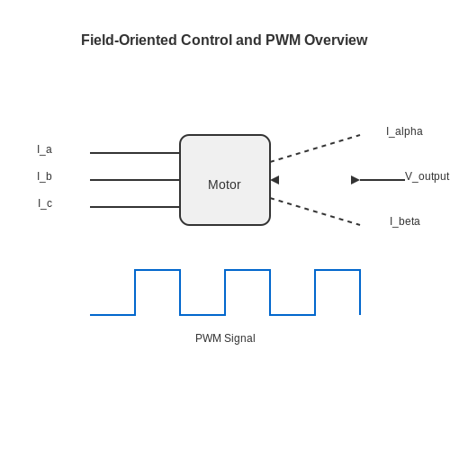
5.2 Firmware Development for Motor Controllers
Developing firmware for brushless DC (BLDC) motor controllers is a critical component in mastering the control, efficiency, and performance of these systems. The firmware serves as the bridge between the hardware and the user-defined control algorithms, enabling features such as speed control, position sensing, fault detection, and communication protocols.
Before delving deeper into the intricacies of the firmware itself, it’s important to highlight the foundational concepts that underpin BLDC motor control. These systems typically employ techniques such as pulse-width modulation (PWM) for power control and field-oriented control (FOC) to optimize torque output. With this understanding, we can begin to formulate the basic structure and functions needed in the firmware.
Understanding Control Algorithms
The choice of control algorithm directly impacts the performance and responsiveness of the motor controller. For BLDC motors, two common approaches are:
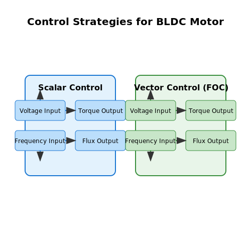
- Scalar Control: This straightforward method primarily adjusts voltage and frequency to control speed.
- Vector Control / Field-Oriented Control (FOC): This advanced method decouples torque and flux, allowing for precise control of motor dynamics and efficiencies across various operating conditions.
Implementing these algorithms requires knowledge of both the mathematical models of the motor and the interaction with the firmware environment. In many cases, the use of a digital signal processor (DSP) or a microcontroller is essential for real-time processing to achieve the desired control response.
Real-Time Operating Systems (RTOS) and Firmware Development
For advanced applications, employing a Real-Time Operating System (RTOS) can provide significant advantages. An RTOS can manage multiple tasks such as sensor readings, motor control loops, and user interface without compromising timing and performance. When developing firmware, consider the following critical components:
- Task Prioritization: Define the critical tasks that require higher priority, such as those affecting motor speed and torque calculations.
- Interrupt Handling: Design effective interrupt service routines (ISRs) to respond to events like hall sensor feedback or temperature limit violations.
- State Management: Keep track of the motor’s operating states (e.g., idle, running, fault) to streamline transitions and maintain system stability.
Integrating these aspects into the firmware will deepen the performance capabilities and reliability of the BLDC motor controller. Testing each component through simulation or incremental prototyping is vital to troubleshoot and refine the algorithms before full-scale production.
Simulation and Emulator Tools
Leveraging simulation tools can significantly streamline firmware development. Tools such as MATLAB/Simulink and PLECS allow for rapid prototyping and provide environments for verifying control strategies before deployment.
Using these tools allows engineers to model dynamic responses and behaviors of BLDC motors under various load conditions. This approach not only aids in identifying optimal control strategies but also in validating the implemented firmware against expected performance metrics.
Documentation and Version Control
Comprehensive documentation practices are imperative both during and after firmware development. Establishing version control provides a clear history of changes, facilitating collaboration among team members and easing future developments and debugging processes. Tools such as Git allow for robust management of code revisions and collaborative efforts.
In conclusion, the complexity involved in firmware development for brushless DC motor controllers necessitates a robust understanding of both hardware functionality and control strategies. Focusing on algorithm performance, task prioritization in RTOS, extensive testing through simulation, and thorough documentation will enhance the reliability and efficiency of the firmware, ultimately leading to superior motor control systems.
5.3 Troubleshooting Common Issues
A Brushless DC (BLDC) motor controller is an essential component in precision motor control applications, enhancing efficiency, reducing maintenance, and increasing longevity. However, like all electronic systems, they can encounter various issues. Understanding common problems and their solutions is paramount for an effective problem-solving approach.
Identifying Symptoms of Failure
Before diving into troubleshooting, it's vital to identify specific symptoms of failure. Common indicators include:
- Motor Not Starting: If the motor fails to start, this might indicate issues with the power supply, controller settings, or connections.
- Erratic Motor Behavior: A motor that runs inconsistently may be affected by sensor errors, noise, or miscommunication between the controller and the motor.
- Overheating: Excessive heat generation often points toward an inefficient driver, overload conditions, or inadequate thermal management.
Common Issues and Solutions
Each of these symptoms can stem from various underlying problems. Here, we will detail the root causes and solutions for each issue.
1. Motor Not Starting
If the BLDC motor is not starting, it is crucial to follow a systematic approach:
- Check the power supply: Ensure that the voltage and current specifications match the motor's requirements. A multimeter can be an invaluable tool for verifying these values.
- Inspect connections: Loose or corroded connections can prevent proper electrical signal transmission. A visual inspection followed by manual wiggling of the connectors can help ascertain their integrity.
- Evaluate controller settings: Analyze the controller parameters, like start-up voltage, acceleration ramp, and initialization sequence. Misconfigured parameters can often cause startup failures.
2. Erratic Motor Behavior
In the event of sporadic motor behavior, consider the following diagnostics:
- Analyze feedback signals: The Hall effect sensors or encoders provide feedback necessary for commutation. Malfunctioning sensors can send incorrect signals leading to erratic operation. Testing the sensors for proper output can aid in identification.
- Check for electromagnetic interference: High-frequency noise from external sources can corrupt signals. Inspect the surrounding circuitry and components for potential interference sources.
- Inspect firmware settings: Ensure the controller's firmware is correctly calibrated for the specific motor type and operating conditions. An update or reconfiguration might be necessary.
3. Overheating
Overheating of the BLDC motor or controller should be addressed promptly, as it can lead to permanent damage:
- Assess load conditions: Operating the motor beyond its rated capacity can induce excessive thermal loads. Compare the current operational load with the rated specifications.
- Implement heat dissipation strategies: If overheating persists, consider improving cooling mechanisms such as air cooling, heatsinks, or liquid cooling systems.
- Verify controller settings: Incorrect settings, particularly the PWM (Pulse Width Modulation) duty cycle, can result in overheating. Adjusting these settings can lead to more efficient operation.
Tools for Troubleshooting
Employing the right tools can significantly streamline the troubleshooting process:
- Multimeter: Essential for measuring voltage, current, and resistance to pinpoint electrical problems.
- Oscilloscope: Useful for observing waveform patterns and ensuring the correct operation of PWM signals.
- Thermal Camera: A valuable non-intrusive tool for identifying overheating components in the system.
In conclusion, effectively troubleshooting common issues in brushless DC motor controllers requires a systematic understanding of both the electrical and mechanical components involved. By employing a logical diagnostic approach, utilizing suitable tools, and addressing symptoms holistically, engineers can enhance the performance and reliability of these sophisticated systems.
6. Recommended Textbooks
6.1 Recommended Textbooks
Brushless DC motors (BLDC) play a crucial role in modern electronics, driving industries ranging from automotive to robotics. For those looking to deepen their understanding of BLDC motor controllers, the following textbooks provide comprehensive insights into their design, operation, and applications. These resources cater to advanced-level readers, offering both theoretical foundations and practical implementations.
- Fundamentals of Electric Drives by Gopal K. Dubey — This book presents a detailed exploration of electric drives, offering insights into control mechanisms and the integration of brushless motors. It efficiently balances theoretical concepts with real-world applications.
- Principles of Electric Machines and Power Electronics by P.C. Sen — A well-regarded reference that extensively covers the fundamentals of electric machines, including BLDC motors, alongside essential power electronics concepts critical for motor control.
- Power Electronics and Motor Drives by Bimal K. Bose — A key reference for understanding the intersections of power electronics and motor drive technologies, including chapters dedicated to the control of BLDC motors.
- Electric Motor Control by Walter N. Alerich — Offers deep insights into various motor control operations with updated methodologies for contemporary challenges in using BLDC motors.
- Advanced Electric Drive Vehicles by Ali Emadi — Focuses on the implementation of electric drive systems in vehicles, with specific sections on BLDC motors that detail both control strategies and efficiency improvements.
- Electric Drives by Ion Boldea — This text delivers comprehensive coverage of electric drive systems and emphasizes the robust control and performance techniques applicable to brushless DC motors.
- Electric Motors and Drives: Fundamentals, Types and Applications by Austin Hughes — A practical and thorough guide to understanding the various types of electric motors, including BLDC motors, with extensive discussion on selection and application considerations.
6.2 Online Resources
- What is a Brushless DC Motor? — This resource provides a comprehensive overview of brushless DC motors, their working principles, and various controller configurations. Suitable for engineers seeking foundational knowledge.
- Brushless DC Motor Principles — Offers detailed insights on the electromagnetic principles behind BLDC motor operation and controller requirements. Includes practical data for real-world applications.
- Engineering Stack Exchange: Brushless DC Motor — An active online community where professionals discuss complex questions and troubleshooting scenarios related to brushless DC motors and their controllers.
- Infineon Technologies: Brushless DC Motor Controllers — Provides a detailed look at different types of BLDC motor controllers offered by Infineon, complete with datasheets and real-world application notes.
- Design and Implementation of a Brushless DC Motor Controller — A research paper detailing the design, development, and testing of a BLDC motor controller. This paper offers practical insights paired with academic rigor.
- Sensorless Control of BLDC Motors — This document from IEEE explores advanced sensorless control methods for BLDC motors, enhancing the understanding of how modern controllers manage high-efficiency operations.
- Microchip: Motor Control and Drive Solutions — Showcases Microchip's portfolio of solutions for motor control, including innovative controllers for BLDC motors. Useful for engineers working with diverse applications.
- Advancements in Motor Control ICs — Reviews the latest advancements in motor control ICs, including those used in brushless DC motors. Perfect for discovering cutting-edge controller technology.
Research Papers and Journals
- Brushless DC Motor Control Technologies — This research paper from ResearchGate provides a comprehensive overview of the latest control technologies for brushless DC motors, focusing on the dynamics, sensor integration, and efficiency optimization methods.
- Performance and Control of BLDC Motors: A Review — An IEEE paper offering an extensive review on the performance and control mechanisms of BLDC motors, covering sensorless control strategies and comparative analyses of various methods.
- Recent Advances in Brushless DC Motor Designs — This article from the Proceedings of the Institution of Mechanical Engineers discusses the recent advances in design and control of BLDC motors, emphasizing innovation in circuit topology and component reliability.
- Energies Journal: Advances in BLDC Motor Efficiency — An academic paper featured in the Energies Journal that investigates the efficiency enhancements in BLDC motors, analyzing various controller designs and their impacts on energy savings.
- Journal of Sound and Vibration: Noise Control in BLDC Motors — This ScienceDirect publication explores the methods of noise reduction in brushless DC motors, focusing on vibration analysis and acoustical optimization.
- Electric Machines and Power Systems: Sensorless Control Techniques — A detailed study on sensorless control techniques for BLDC motors, published by Taylor & Francis, highlighting innovative algorithms and real-world applications.
- IEEE Transactions on Industrial Electronics: Advanced BLDC Motor Drives — An IEEE Transactions paper that reviews the advancements in BLDC motor drive systems, addressing the challenges in digital control and real-time implementation.