Capacitance and Charge
1. Definition of Capacitance
1.1 Definition of Capacitance
Capacitance, an essential concept in both electronics and electromagnetism, quantifies the ability of a system to store electrical energy in an electric field. Defined as the ratio of the electric charge stored (Q) to the potential difference (V) across the conductors, capacitance is given by the equation:
Here, C represents capacitance measured in farads (F), Q is the charge in coulombs (C), and V is the voltage in volts (V). This simple relationship reveals a profound insight into how capacitors function in electronic circuits — the higher the charge that a capacitor can store at a given voltage, the greater its capacitance.
The historical context of capacitance traces back to the work of scientists like Henry Cavendish and Michael Faraday. Faraday's experiments in the early 19th century led to the development of the concept of the electric field, reinforcing the understanding of how different materials can influence capacitance. For instance, the presence of a dielectric material between capacitor plates significantly enhances capacitance beyond the value determined solely by the area and separation of the plates.
Understanding the Physical Representation
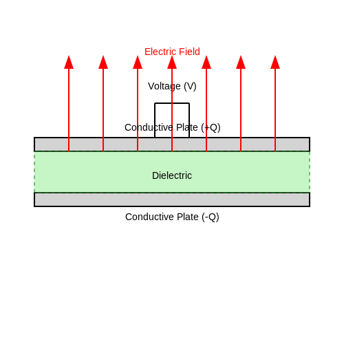
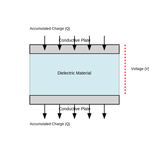
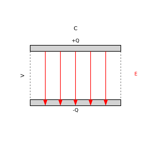
Capacitance can be visually represented through the model of a parallel plate capacitor. Imagine two conductive plates placed parallel to each other, separated by a certain distance. When a voltage is applied across these plates, an electric field is established, resulting in a proportional charge accumulation. This geometry provides a clear depiction of how the area of the plates and the distance between them influences capacitance:
Capacitance increases with larger plate area, as more charge can be stored, while it decreases with greater separation, which weakens the electric field strength between the plates. To visualize this concept:
Practical Applications of Capacitance
Understanding capacitance is crucial for various applications, particularly in the design of circuits. Capacitors are extensively used in filtering applications, energy storage systems, timing circuits, and signal coupling/decoupling. Their ability to smooth out voltage fluctuations is fundamental in power supply design, where rapid changes in load demand require capacitors to either supply or absorb charge to maintain stable operation.
In advanced electronics, such as integrated circuits, microelectronic devices utilize capacitors on a nanoscopic scale. These components offer the capability to enhance performance but also present challenges related to parasitic capacitance, which can lead to unwanted signal distortion and power loss if not managed correctly.
Moreover, the capacitance values are tailored depending on the intended function; for example, in RF applications, varying capacitance values are crucial for tuning circuits to desired frequencies. As technology evolves, the manipulation and understanding of capacitance become ever more critical in developing high-performance electronic devices.
Conclusion
In summary, capacitance is a critical parameter reflecting a system’s ability to store electrical energy. Its mathematical formulation and physical implications underpin vast applications in electrical engineering. The interplay of capacitance with materials and geometric configurations significantly enhances our capability to engineer effective electronic systems.
1.2 The Capacitor's Role in Circuits
The capacitor is a fundamental electronic component widely used in various applications that require the storage of electrical energy. In circuits, capacitors serve several key roles, which can significantly impact a system’s performance. Understanding these functions is essential for any advanced practitioner in the field of electronics and circuit design.
Energy Storage and Release
At its core, a capacitor stores energy in the electric field created between its plates when connected to a voltage source. The unique property of capacitors allows them to release this stored energy quickly when required. This behavior results in transient response characteristics that are critical in applications like timing circuits and filters.
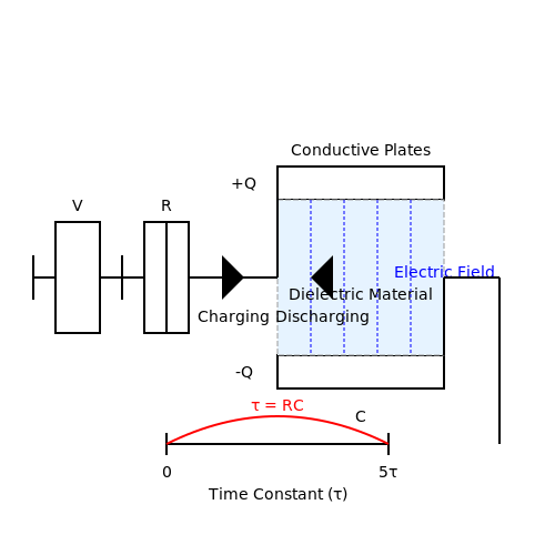
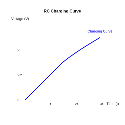
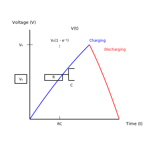
In a simple RC (resistor-capacitor) circuit, the voltage across a capacitor V over time t can be described by the equation:
Here, V_0 is the initial voltage, R is the resistance, and C is the capacitance. This RC time constant (τ = RC) dictates how quickly the capacitor charges or discharges, influencing circuit behavior during switching operations.
Filtering Applications
In AC circuits, capacitors are often used in filtering applications to smooth out voltage fluctuations. They can filter out high-frequency noise, allowing only signals of certain frequencies to pass, which is particularly beneficial in power supply systems.
For instance, a capacitor placed in parallel with a load can improve power quality by absorbing voltage spikes and providing reactive power. This behavior can be formally described using impedance:
Where Z_C is the impedance of the capacitor, j is the imaginary unit, and ω is the angular frequency of the applied voltage. This equation highlights the frequency-dependent behavior of capacitors, enabling their use in tunable filters and frequency dividers.
Timing Applications
The timing capabilities of capacitors have led to their use in oscillators and timers. For example, in a 555 timer circuit, capacitors regulate the timing interval between output pulses. By selecting appropriate resistance and capacitance values, designers can set an accurate time delay or frequency of operation, showcasing the versatility of capacitors in circuit design.
Capacitors in Signal Coupling and Decoupling
Signal coupling and decoupling are other essential functions in which capacitors play a critical role. In a coupling application, a capacitor allows AC signals to pass while blocking DC. This can be seen in audio circuits where it prevents noise from the power supply from affecting the audio signal.
In decoupling, capacitors reduce voltage fluctuations due to fast digital transitions by providing local energy storage for integrated circuits, ensuring stable operation. The use of decoupling capacitors is a standard practice in PCB design to manage noise and improve signal integrity.
Conclusion
The role of capacitors in circuits extends well beyond simple energy storage. Their ability to shape voltage responses, filter frequencies, and manage signal integrity makes them indispensable components in modern electronic design. Their diverse applications continue to evolve as new technologies emerge, highlighting the necessity for engineers and researchers to understand their critical functionalities fully.
1.3 Capacitor Types and Their Applications
Capacitors play a pivotal role in a myriad of electronic setups, owing to their ability to store and release electrical energy with precision. Understanding the different types of capacitors, their distinct characteristics, and their relevant applications aids in making informed design decisions in a wide range of engineering fields. In this subsection, we will explore various capacitor types, highlighting their construction, operational features, and specific applications.
Electrolytic Capacitors
Electrolytic capacitors are polarized capacitors that contain a liquid electrolyte, which provides a high capacitance value relative to their physical size. They are characterized by their ability to handle significant amounts of voltage and charge. The construction involves a thin oxide layer on the anode, which acts as a dielectric material, allowing for larger capacitance values.
A common application of electrolytic capacitors is in power supply circuits, where they smooth out voltage fluctuations. They are also utilized in audio systems for coupling and decoupling applications, effectively managing DC levels while allowing AC signals to pass.
Ceramic Capacitors
Ceramic capacitors are non-polarized capacitors, typically constructed using ceramic materials as the dielectric. They exhibit a wide range of capacitance values and are known for high stability and reliability even under temperature and voltage fluctuations. The most common type is a multi-layer ceramic capacitor (MLCC), which stacks multiple layers of dielectric and conductive materials to achieve higher capacitance.
These capacitors are widely used in high-frequency applications, including RF circuits, filters, and decoupling applications. Their small size and low costs make them ideal for modern electronic devices like smartphones and tablets.
Film Capacitors
Film capacitors utilize a thin plastic film as the dielectric material. This construction results in excellent electrical properties, making them ideal for applications needing precise capacitance values and high-temperature stability. Film capacitors can also handle high frequencies and have low equivalent series resistance (ESR).
Common applications include audio circuits, timing applications, and in power electronics as filter capacitors. Their durability and resistance to environmental stresses give them a significant edge in demanding applications, such as automotive electronics.
Tantalum Capacitors
Tantalum capacitors are known for their compact size and high capacitance per volume. Constructed from tantalum powder, they provide excellent stability and reliability. Tantalum capacitors are polarized, similar to electrolytic capacitors, and should be connected with the correct polarity to avoid failure.
These capacitors find use in portable electronic devices, medical implants, and aerospace applications due to their lightweight and small footprint. They are preferred where space is at a premium and reliability is crucial.
Supercapacitors
Supercapacitors, also known as electric double-layer capacitors (EDLCs), have a much higher capacitance than traditional capacitors due to their ability to store energy electrostatically. They bridge the gap between conventional capacitors and batteries, offering rapid charge and discharge cycles.
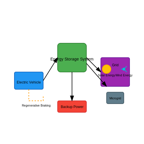
Supercapacitors are commonly used in applications requiring quick bursts of energy, like regenerative braking systems in electric vehicles, energy storage in renewable energy systems, and backup power supplies. Their long cycle life and high power density make them a valuable asset in modern electronics.
Applications Summary
- Power Supply Circuits: Electrolytic capacitors for voltage smoothing.
- High-Frequency Circuitry: Ceramic capacitors in RF applications.
- Audio Equipment: Film capacitors for superior sound quality.
- Compact Electronics: Tantalum capacitors for high-capacitance needs.
- Energy Storage: Supercapacitors for rapid discharge applications.
In summary, the selection of a capacitor type largely depends on the specific needs of the electronic circuit, including requirements for capacitance, voltage rating, size, and environmental durability. As technology progresses, the development of new materials and innovative designs continue to optimize the performance of capacitors across various applications.
2. Nature of Electric Charge
2.1 Nature of Electric Charge
The nature of electric charge forms the foundation of electrostatics and is crucial for understanding capacitance and its applications. Electric charge is a fundamental property of matter, presenting itself in two forms, commonly referred to as positive and negative. The ancient Greek philosopher Thales recognized static electricity by rubbing amber and observed its attractive properties. Today, we know that electric charge causes particles to exert forces on one another, a phenomenon integral to the structure of atoms and the behavior of materials.
Types of Electric Charge
Electric charge can be characterized by several key properties:
- Quantization of Charge: Electric charge is quantized, meaning it exists in discrete units. The elementary charge, denoted as \( e \), is approximately equal to \( 1.602 \times 10^{-19} \) coulombs (C). A proton carries a charge of \( +e \), while an electron carries a charge of \( -e \).
- Conservation of Charge: In any closed system, the total charge remains constant. Charge cannot be created or destroyed, only transferred from one body to another.
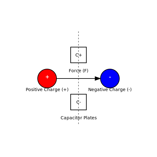
- Attraction and Repulsion: Charges of the same sign repel each other, while charges of opposite signs attract. This principle is quantified by Coulomb's law, which describes the electrostatic interaction between charged particles.
Coulomb’s Law
To quantify the interaction between two point charges, we employ Coulomb's law. This law states that the electrostatic force \( F \) between two charges \( q_1 \) and \( q_2 \) separated by a distance \( r \) is given by:
Here, \( k \) is Coulomb's constant, approximately \( 8.99 \times 10^9 \, \text{N m}^2/\text{C}^2 \). This equation demonstrates that the force is directly proportional to the product of the magnitudes of the charges and inversely proportional to the square of the separation distance. This inverse square relationship is reminiscent of gravitational force, emphasizing the interconnectedness of fundamental forces in nature.
Implications in Capacitors
Understanding the nature of electric charge is vital when studying capacitors, which store electrical energy through the separation of charges. In capacitors, opposite charges accumulate on two conductive plates, creating an electric field between them. The relationship between capacitance (\( C \)), charge (\( Q \)), and potential difference (\( V \)) is defined by the equation:
Where \( C \) is measured in farads (F). This relationship emphasizes not only the importance of charge but also how different configurations of materials can enhance capacitance. As capacitors are essential components in various electronic circuits—serving purposes from energy storage to filtering—they highlight the practical relevance of understanding electric charge.
Conclusion
The nature of electric charge is a fundamental concept that underpins various aspects of physics and engineering. From theoretical exploration in electrostatics to practical applications in capacitors and electronic devices, mastering the behavior of electric charge is essential for advancing in fields like electrical engineering and materials science.
2.2 Charge Quantization and Conservation
The concepts of charge quantization and conservation serve as foundational principles in understanding electrostatic phenomena and the workings of electronic devices. Charge quantization refers to the discrete nature of electric charge, where it only occurs in integer multiples of a fundamental charge, primarily represented by the charge of the electron, approximately \( e = 1.602 \times 10^{-19} \, \text{C} \).
Charge Quantization: This phenomenon postulates that no matter how small an electric charge may be, it can never exist as a fraction of the elementary charge. Thus, a system can hold charges represented as \( Q = ne \), where \( n \) is an integer and \( e \) is the elementary charge. This concept elegantly contrasts the continuous models often employed in classical physics, bridging a crucial gap between macroscopic phenomena and quantum mechanical behavior.
Historical Context
The quantization of charge was significantly substantiated by Robert Millikan's oil drop experiment in the early 20th century. By measuring the charge on oil droplets, Millikan demonstrated that charge indeed occurs in distinct quantized amounts, leading to a deeper understanding of atomic structure and the nature of electricity. His findings laid the groundwork for modern theories of electromagnetism and particle physics.
Charge Conservation
In conjunction with charge quantization, the principle of charge conservation asserts that electric charge can neither be created nor destroyed in an isolated system. Mathematically stated, the total charge \( Q_{\text{total}} \) in a closed system remains constant over time:
This principle is not merely a theoretical construct; it has profound implications in various fields of physics and engineering, including circuit design, electromagnetism, and subatomic particle reactions. For instance, in an electric circuit, the sum of the charges entering any junction must equal the sum of charges leaving that junction, conforming to Kirchhoff's current law.
Real-World Applications
- Electronic Components: Capacitors utilize the principles of charge quantization in their functioning. The stored charge in a capacitor is quantized, allowing for precise and consistent performance across electrical systems.
- Semiconductor Physics: The behavior of electrons and holes in semiconductors can be described using quantized charge states, which is critical for the development of transistors and diodes.
- Particle Physics: Understanding charge conservation is essential in predicting outcomes in high-energy physics experiments, such as particle collisions within accelerators.
In conclusion, the interplay between charge quantization and conservation not only enriches the foundational knowledge of electrostatics but also influences a multitude of technological advancements. By grasping these concepts, engineers and physicists can better innovate and resolve challenges in electrical engineering and beyond.
2.3 Charging Methods: Conduction, Induction, and Friction
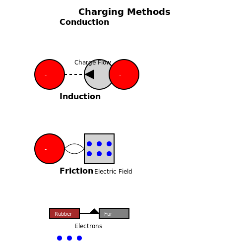
Understanding how charge is transferred to capacitors is critical in both experimenting and practical implementations within electrical systems. This section deep dives into three principal methods of charging: conduction, induction, and friction. Each method not only highlights background principles of electrostatics but also illustrates practical applications in technologies ranging from consumer electronics to industrial systems.
Conduction Charging
Conduction charging occurs when two objects make direct contact, allowing charge to flow from one body to another due to the difference in electric potential. This phenomenon is described by Coulomb's Law, which states that the electrostatic force between two charges is directly proportional to the product of the charges and inversely proportional to the square of the distance between them.
Where:
- F = electrostatic force between the charges
- q1 and q2 = magnitudes of the charges
- r = distance between the charges
- k = Coulomb's constant, approximately \( 8.99 \times 10^9 \, \text{N m}^2/\text{C}^2 \)
In practice, conduction charging is primarily used in everyday applications, such as charging batteries through direct contact. The effectiveness relies on the materials involved; for instance, metals with free electrons conduct charge effectively, while insulators resist this transfer.
Induction Charging
In contrast to conduction, induction charging occurs without direct contact. This method involves bringing a charged object near a neutral conductor, resulting in charge separation within the conductor. When the charged object is brought close enough, the electric field it generates induces a polarization of charges within the conductor, with some electrons moving towards or away from the charged object.
This process can be further explored through the principle of mutual induction. For instance, in transformers, varying current in one coil produces a varying magnetic field that induces voltage in another coil situated nearby. This is governed by the equations of electromagnetic induction, particularly Faraday's law, which asserts that a change in magnetic flux through a circuit will induce an electromotive force (EMF).
Where:
- ℰ = induced EMF
- ΦB = magnetic flux
- t = time
Induction charging is widely applied in wireless charging technologies, such as those used in electric toothbrushes, smartphones, and electric vehicles. By utilizing magnetic fields, these systems avoid wear and tear from physical connections, enhancing durability and convenience.
Friction Charging
Friction charging, also known as triboelectric charging, occurs when two different materials are rubbed together, causing charges to transfer from one material to another. This method is fundamental to the triboelectric effect, where certain materials become positively or negatively charged based on their position in the triboelectric series.
For instance, when rubber is rubbed with fur, the rubber may acquire a negative charge while the fur obtains a positive charge. The basic principle behind this method is rooted in the differing affinities of materials to lose or gain electrons, making it essential in applications related to static electricity, such as in photocopiers and air purifiers.
Though friction charging may seem simple, its implications can be significant in industrial settings, where static electricity can lead to dangerous sparks or material repulsion, necessitating careful control and management.
As we can see, each charging method plays a role in the broader field of electronics. Understanding these principles not only informs theoretical knowledge but also shapes practical applications across myriad technologies, ensuring that engineers and researchers are well-equipped to address real-world challenges.
3. Capacitance Formula: C = Q/V
3.1 Capacitance Formula: C = Q/V
To thoroughly understand capacitance in electrical circuits, we must first delve into the fundamental relationship expressed in the capacitance formula:Deriving the Capacitance Formula
We can derive the capacitance formula starting from the fundamentals of how capacitors operate. A capacitor consists of two conductive plates separated by an insulating material (dielectric). When a voltage \( V \) is applied across the plates, an electric field is established between them. 1. Electric Field and Charge: The electric field \( E \) generated between the plates is related to the voltage across the capacitor and the distance \( d \) between the plates:Practical Relevance and Applications
Capacitance is pivotal in numerous technological applications. For engineers and designers, understanding how to manipulate capacitance is critical in circuit design. Capacitors are widely used in:- Energy Storage: Capacitors store energy in electronic devices, such as power supplies and flash photography.
- Filtering: In signal processing, capacitors help filter signals, blocking DC while allowing AC to pass via high-pass and low-pass filters.
- Timing Circuits: In combination with resistors, capacitors define time constants in oscillators and timers, such as in 555 timer circuits.
In summary, the capacitance of a capacitor quantifies its ability to store charge per unit voltage, encapsulated succinctly in the formula \( C = Q/V \). Understanding this relationship is essential for innovating and refining electronic devices across various industries.
3.2 Influence of Dielectric Materials
Understanding the influence of dielectric materials on capacitance is crucial for enhancing the performance of a variety of electrical components. Dielectrics, insulators that can be polarized by an electric field, are integral in enabling capacitors to store charge effectively. Their presence alters key electrical properties, elevating capacitor functionality in many applications. The mathematical foundation of dielectric influence is founded on the concept of relative permittivity, also known as the dielectric constant (\(\varepsilon_r\)). The capacitance \(C\) of a parallel-plate capacitor is originally formulated without any dielectric as: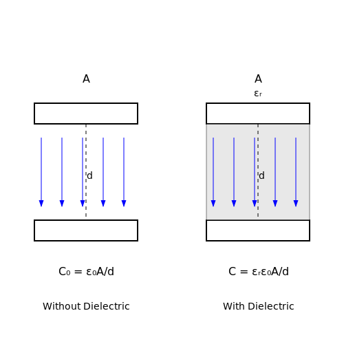
3.3 Energy Storage in Capacitors
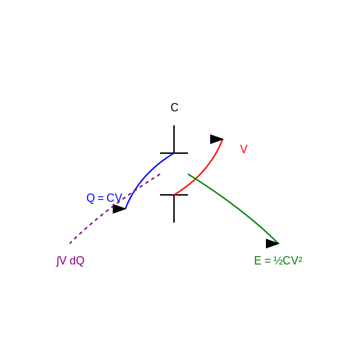
Capacitors are fundamental components in electronic circuits, known for their ability to store electrical energy. When a capacitor is connected to a voltage source, it accumulates charge on its plates, creating an electric field between them. The energy stored in a capacitor is a crucial concept with far-reaching implications in various applications, from power supplies to electronic filtering and signal processing.
Understanding Energy Storage
The energy (\(E\)) stored in a capacitor is linked to the amount of charge (\(Q\)) it holds and the voltage (\(V\)) across its plates. To derive the formula for this energy, we start with the basic relationship between charge and voltage:
Here, \(C\) is the capacitance measured in farads (F). The energy is acquired by integrating the work done to move a small amount of charge \(dq\) as it is moved against the voltage \(V\). This work is given by the product of voltage and the charge moved:
Substituting \(V\) with \(Q/C\) gives:
To find the total energy stored as charge accumulates from zero to \(Q\), we integrate:
This amounts to:
Employing the original charge-voltage relationship \(Q = CV\) enables us to express energy in terms of voltage:
This equation reveals that the energy stored in a capacitor increases quadratically with voltage. As the voltage doubles, the energy stored quadruples, exemplifying the importance of voltage management in capacitor applications.
Practical Applications of Capacitor Energy Storage
The capability of capacitors to store energy has numerous practical applications:
- Power Supply Smoothing: Capacitors are often used in power supply circuits to smooth out fluctuations in voltage. They act as reservoirs of charge, compensating for varying load conditions.
- Energy Storage Systems: In renewable energy setups, capacitors are utilized alongside batteries to store energy for quick release, especially beneficial in applications requiring short bursts of power.
- Timing Circuits: Capacitors are pivotal in RC (resistor-capacitor) timing circuits, where the time constant is defined by the product of resistance and capacitance, effectively controlling timing and frequency in various applications.
- Signal Filtering: In communication systems, capacitors are essential for filtering signals; they allow AC signals to pass while blocking DC components, crucial for signal integrity.
- Audio Equipment: In audio systems, capacitors are integrated into crossovers within speakers, ensuring that different frequencies are routed to appropriate drivers (woofers, tweeters).
The influence of capacitors extends beyond basic circuits. In recent advancements, the development of supercapacitors has raised the practical energy storage capabilities much higher, paving the way for applications in electric vehicles and portable electronic devices where high power delivery is essential.
As technology evolves, understanding the principles governing energy storage in capacitors is pivotal, not only for circuit design but also for the innovation of new energy storage technologies that could transform the landscape of electronics and energy management.
Energy Storage Equation Summary
The equation representing the energy stored in a capacitor is summarized as follows:
This foundational formula encapsulates the relationship between capacitance, voltage, and energy, serving as a cornerstone for both theoretical investigation and practical application in fields ranging from consumer electronics to advanced engineering solutions.
4. RC Circuits and Time Constants
4.1 RC Circuits and Time Constants
RC circuits, composed of resistors (R) and capacitors (C), are fundamental in both analog and digital electronics. They serve various purposes, including filtering signals, timing applications, and charging/discharging energy storage devices. Understanding the behavior of RC circuits is critical for anyone engaging with electronic design or analysis.
At the core of RC circuits is the relationship between capacitance, charge, and voltage. In order to delve deeply into the time-related aspects of these circuits, we need to explore how they respond to changes in voltage over time, which is characterized by the time constant represented as τ (tau).
Defining Time Constant τ
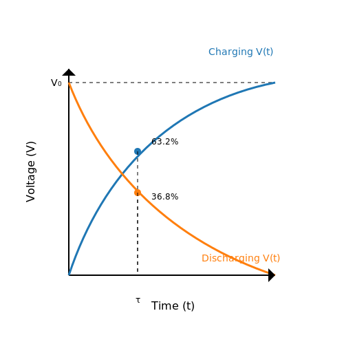
The time constant is defined as the time required for the voltage across the capacitor to reach approximately 63.2% of its final value during charging or to decrease to about 36.8% of its initial voltage during discharging. Mathematically, the time constant can be expressed as:
Here, R is the resistance in ohms (Ω) and C is the capacitance in farads (F). The product of resistance and capacitance effectively defines the rate at which the voltage changes in the circuit.
Charging Behavior of an RC Circuit
When a voltage source is connected to an RC circuit, the capacitor begins to charge. The voltage across the capacitor, V(t), at any time t while charging can be described by the following equation:
In this equation, V0 is the final steady-state voltage when the capacitor is fully charged, and e is the base of the natural logarithm. The exponential term captures the diminishing returns as the capacitor approaches the final voltage.
Discharging Behavior of an RC Circuit
Conversely, when the voltage source is removed and the capacitor discharges through the resistor, the voltage across the capacitor varies according to:
In this situation, the voltage exponentially decays as time progresses, with V0 again being the initial voltage across the capacitor at the moment discharge begins.
Practical Applications of RC Circuits
RC circuits are widely employed in applications such as:
- Time Delay Circuits: Utilized in timers, for instance, in electronic gadgets to ensure a specific delay before action is taken.
- Filter Circuits: Serving to separate frequencies in audio electronics, helping to eliminate noise or optimize signal quality.
- Signal Conditioning: Enhancing the quality of signals in data acquisition, ensuring accurate readings and efficient processing.
The understanding of time constants in RC circuits also facilitates the design of more complex filter and timing circuits, integral to the functioning of advanced electronic systems used in communications, control systems, and signal processing applications.
In summary, RC circuits not only embody core principles of capacitance and charge but also illustrate invaluable concepts in signal processing and timing applications. The interplay between resistance and capacitance, governed by the time constant τ, helps engineer solutions across a multitude of technologies.
4.2 Capacitors in AC Circuits
Capacitors play a pivotal role in alternating current (AC) circuits, serving functions that extend beyond mere energy storage. When examining how capacitors operate within AC systems, it’s essential to consider both the mathematical and physical implications. Capacitors interact uniquely with AC signals due to their inherent ability to store electric charge and discharge it in response to varying voltage levels, which can lead to phase shifts and reactive power components.
Understanding Capacitive Reactance
In the realm of AC circuits, capacitors do not behave the same way as they do in direct current (DC) circuits. A key parameter to understand is the capacitive reactance (\(X_C\)), which quantifies how much a capacitor resists the flow of AC. Capacitive reactance is defined as:
where:
- \(X_C\) is the capacitive reactance (measured in ohms),
- f is the frequency of the AC signal (in hertz), and
- C is the capacitance (in farads).
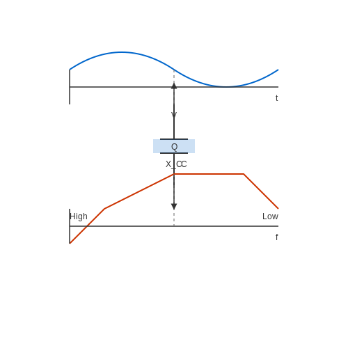
This equation shows that the reactance decreases with increasing frequency, indicating that capacitors allow higher frequency signals to pass through more easily while blocking lower frequency signals. This property is particularly useful in signal filtering and tuning applications.
Phase Shift Between Voltage and Current
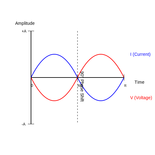
Another crucial aspect of capacitors in AC circuits is the phase shift they introduce between voltage and current. In a purely capacitive circuit, the current leads the voltage by 90 degrees (or \(\frac{\pi}{2}\) radians). This can be understood through the relationship of voltage (\(V\)) and current (\(I\)):
Here, \(I(t)\) represents the instantaneous current, and \(V(t)\) is the instantaneous voltage across the capacitor. As the capacitor charges and discharges, the current reaches its maximum earlier than the voltage. This behavior is essential in applications such as oscillators and in power factor correction.
Practical Applications of Capacitors in AC Circuits
Capacitors are leveraged in a range of practical applications within AC circuits:
- Power Factor Correction: Capacitors can offset inductive loads, improving energy efficiency in industrial applications.
- Filter Circuits: In audio equipment, capacitors can filter out unwanted frequencies, allowing only the desired signals to pass.
- Tuning Circuits: Used in radios and televisions, capacitors help select specific frequencies for reception, which is vital in communication systems.
These applications highlight the importance of understanding the behavior of capacitors in alternating current environments. Engineers must consider both the phase relationships and the frequency-dependent reactance to design effective AC circuits.
Conclusion
Understanding the role of capacitors in AC circuits is vital for advanced circuit design. With their ability to influence phase relationships and provide frequency-dependent resistance, capacitors are invaluable components in various electronic systems. Mastery over these concepts leads to more effective and responsive circuit designs, fostering innovations in electronics and communication technologies.
4.3 Filters and Timing Applications
In the realm of electronics, capacitors serve a multitude of purposes beyond simple energy storage, particularly in filters and timing applications. Their ability to charge and discharge at varying rates makes capacitors integral to controlling signal flow, adjusting frequency responses, and establishing timing sequences in circuit design.The Role of Capacitors in Filters
Filters are circuits specifically designed to allow signals of certain frequencies to pass while attenuating others. The frequency response of a filter depends heavily on the arrangement of capacitors and other components like resistors and inductors. Two fundamental types of filters that utilize capacitors include:- Low-Pass Filters (LPF): These circuits allow signals with a frequency lower than a certain cutoff frequency, while attenuating signals with frequencies higher than the cutoff. The capacitor in an LPF shunts high-frequency signals to ground, preventing them from reaching the output.
- High-Pass Filters (HPF): Conversely, HPFs permit the passage of high-frequency signals while blocking low-frequency ones. Here, the capacitor blocks DC (0 Hz) and passes AC signals, shaping how signals propagate through a system.
Capacitors in Timing Applications
In addition to filtering, capacitors play a vital role in timing applications, such as those seen in oscillator circuits and timer devices. A simple RC timing circuit used in generating time delays can illustrate this functionality. When a capacitor is charged through a resistor, the voltage across the capacitor rises exponentially according to the following relationship:Practical Relevance and Applications
The applications of capacitors in filters and timing is extensive: - Audio Engineering: Low-pass filters are used in audio circuits to eliminate high-frequency noise, ensuring that desired audio signals are clean and clear. - Signal Processing: Capacitors flood high-frequency signals in RF applications to maintain safe levels, aligning with legal transmission standards. - Digital Systems: Timing circuits based on capacitors form the backbone of digital clock generation, providing critical signals for synchronization. - Communication Systems: Filters designed with capacitors control which frequencies are manipulated in signal processing, enhancing the quality of transmitted data. In summary, an understanding of capacitors in filtering and timing applications is crucial for numerous engineering fields. Through careful selection and design of RC circuits, engineers can tailor responses and controls that meet specific technical demands, ensuring that circuits behave predictably and effectively.5. Common Capacitor Failures
5.1 Common Capacitor Failures
Capacitors play a crucial role in electrical circuits, storing and releasing electrical energy to support various functionalities. Understanding the common failure modes of capacitors is essential for engineers and researchers involved in electronics design, maintenance, and troubleshooting. The reliability of capacitors can significantly impact circuit performance, particularly in high-frequency applications or power electronics.
Understanding Capacitor Failures
Capacitors can fail due to various physical mechanisms, and understanding these can lead to more effective design and selection choices. Common failure modes include:
- Dielectric Breakdown: This occurs when the electric field across the dielectric material exceeds its breakdown voltage, leading to permanent failure.
- Capacitance Loss: Factors such as temperature, frequency, and voltage can influence capacitance. Over time or under stress, capacitors can experience a significant drop in capacitance, impacting performance.
- Leakage Current Increase: Ideally, capacitors should block DC current; however, as they age, unwanted leakage current can rise, leading to power loss and overheating.
- Electrolytic Drying: In electrolytic capacitors, the electrolyte can evaporate, reducing capacitance and leading to failure.
- Mechanical Failure: External stresses, either from temperature cycles or PCB flexing, can lead to physical cracks or lead separation, particularly in surface-mount capacitors.
Failure Mechanisms in Detail
To appreciate why these failures occur, it’s essential to delve deeper into the mechanisms:
1. Dielectric Breakdown
Dielectric breakdown happens when the insulation capabilities of the dielectric material fail. For example, in a ceramic capacitor, if the electric field becomes too strong, it can cause a short circuit. This phenomenon not only leads to failure but can also damage other components in the circuit.
Here, \( V_{br} \) is the breakdown voltage, \( E_{max} \) is the maximum electric field, and \( d \) is the thickness of the dielectric. When \( V_{br} \) is exceeded, catastrophic failure can ensue.
2. Capacitance Loss
Capacitance is influenced by temperature, voltage, and frequency. The equivalent series resistance (ESR) and equivalent series inductance (ESL) also play crucial roles in determining loss characteristics. A loss in capacitance can lead to greater ripple currents, causing overheating and accelerating aging processes.
3. Leakage Current Increase
Capacitors ideally have very low leakage currents, but as they degrade, these currents grow, resulting in energy dissipation as heat. This heating effect exacerbates aging, potentially leading to a thermal runaway condition in improperly rated capacitors.
4. Electrolytic Drying
In electrolytic capacitors, the chemical composition of the electrolyte can degrade over time, leading to reduced capacitance. This is particularly relevant in applications where capacitors are subject to high temperatures or high ripple currents.
5. Mechanical Failure
Mechanical stresses can lead to failures like cracking, especially in surface-mounted devices where soldering can induce stress during thermal cycling. Proper PCB design and assembly practices can mitigate these risks.
Real-World Implications
The implications of capacitor failure are significant. In critical applications such as power supply circuits or audio processing, a failing capacitor can lead to degraded performance or complete system malfunction. Therefore, regular testing, maintenance, and the choice of high-quality components with better reliability ratings are paramount.
Final Thoughts
Understanding common capacitor failures not only enhances circuit reliability but also informs design decisions. Engineers must consider these failure mechanisms during the design and selection processes to improve the lifespan and performance of their electronic devices.
5.2 Diagnosing Capacitor Problems
Diagnosing capacitor issues is essential for maintaining the reliability and efficiency of electronic systems. Capacitors, being critical components that store and release electrical energy, can fail or degrade due to various factors, including aging, environmental conditions, and electrical stress. Understanding the signs of faulty capacitors and employing correct diagnostic techniques can save time and prevent cascading failures in electronic devices.
Identifying Symptoms of Capacitor Failure
A failed capacitor can manifest several observable symptoms. Recognizing these early can help in preventive maintenance. Here are some common indicators:
- Physical Damage: Bulging or leaking electrolytic capacitors can indicate overheating or excessive voltage.
- Decreased Performance: A noticeable drop in performance or increased output ripple voltage may signify failing capacitors, particularly in power supply circuits.
- Unusual Noises: Whining or buzzing sounds from capacitors might suggest that they are failing under load.
- Circuit Behavior: Unexpected resets, shutdowns, or erratic behavior in circuits are often traced back to defective capacitors.
Testing Capacitors
Once the symptoms of capacitor failure are observed, the next step is to conduct tests to confirm the diagnosis. The most common methods include:
1. Visual Inspection
A thorough inspection of the capacitor's physical condition can show whether it has bulged, leaked, or discolored. It is critical to perform this inspection carefully, as some faults may not be apparent without close examination.
2. Multimeter Testing
A digital multimeter (DMM) can be employed to test capacitance and resistance values. Here’s a straightforward method to measure capacitance:
- Disconnect the capacitor from the circuit to eliminate the effects of parallel connections.
- Set the multimeter to the capacitance setting (often indicated by "C" or a capacitor symbol).
- Connect the multimeter leads to the capacitor terminals (positive to positive, negative to negative).
- Observe the reading and compare it with the capacitor's rated value.
If the reading is significantly lower than the specified value, the capacitor may be failing. For a more definitive analysis, testing leakage current or equivalent series resistance (ESR) is also beneficial.
3. ESR Testing
The Equivalent Series Resistance (ESR) of a capacitor indicates its health. A higher ESR can signify aging or damage, even if capacitance is within acceptable limits. This characteristic is especially relevant for electrolytic types. To measure ESR, specific ESR meters are available:
- Disconnect and discharge the capacitor.
- Connect the ESR meter’s leads to the capacitor terminals.
- Take a reading and compare it to manufacturer specifications.
Practical Applications of Capacitor Diagnostics
Capacitor diagnostics extends beyond simple repairs. In design and engineering, routinely assessing capacitors can inform decisions on component selection, lifecycle planning, and circuit optimization. Understanding the operational environment of a capacitor—be it temperature, voltage, or frequency—can lead to smarter design choices that extend the life of electronic devices.
In summary, diagnosing capacitor problems involves a blend of observational skills, testing methodologies, and a fundamental understanding of circuitry. By implementing a robust diagnostic routine, engineers can enhance the reliability of their designs and ensure the longevity of electronic systems.
5.3 Replacing and Upgrading Capacitors
Capacitors are pivotal components in electronic circuits, serving various roles such as energy storage, power conditioning, and noise filtering. As technology evolves, the need for replacing or upgrading capacitors becomes increasingly relevant, particularly in enhancing circuit performance and reliability. Understanding the various factors that influence capacitor selection and implementation can lead to better design choices and greater efficiency in applications ranging from consumer electronics to aerospace systems.
Selection Criteria for Replacement
When considering the replacement or upgrade of capacitors, several key criteria should guide the decision-making process:
- Voltage Rating: The replacement capacitor must have a voltage rating that meets or exceeds the original capacitor’s specifications. Exceeding the voltage rating can lead to catastrophic failures.
- Capacitance Value: The chosen capacitor should have the same capacitance value as the original unless design requirements specify otherwise. This ensures that the circuit maintains its intended performance.
- Physical Size: Upgrading capacitors might involve considerations around physical dimensions. Higher capacitance values often require larger packages, affecting PCB layout and design.
- Temperature and Endurance Ratings: Capacitors are rated for specific operational temperature ranges, and their failure rates can increase significantly outside of these limits. Choosing capacitors with enhanced endurance can improve reliability.
Types of Capacitors for Upgrading
With advancements in materials and manufacturing processes, several types of capacitors are available for upgrade. Here are some commonly used types:
- Electrolytic Capacitors: Known for their high capacitance values, electrolytic capacitors are prevalent in power supply applications. Upgrading to low-ESR variants can enhance performance in switching power supplies.
- Ceramic Capacitors: With improvements in dielectric materials, newer ceramic capacitors provide lower losses and higher capacitance densities. They are an excellent choice for high-frequency applications.
- Tantalum Capacitors: Known for their reliability and stable electrical characteristics, tantalum capacitors can be used in applications where space is at a premium. However, care should be taken regarding their higher cost and derating under certain conditions.
Practical Implementation Considerations
Replacing or upgrading capacitors involves practical considerations beyond specifications:
- Soldering Techniques: Proper soldering techniques are essential for avoiding thermal damage to sensitive components. Ensuring that the correct soldering temperature and time are used is critical.
- Testing and Validation: After replacing capacitors, it is crucial to test the circuit under operational conditions. Validation through performance testing can identify potential issues early.
- Power Supply Influence: The power supply circuit may require reevaluation, as changes in capacitance can impact ripple and transient responses. This examination ensures overall system stability.
Conclusion
Upgrading and replacing capacitors is an essential aspect of circuit design and maintenance in electronics. By honing in on the selection criteria, understanding the available options, and being mindful of practical implementation aspects, engineers can significantly enhance circuit performance and reliability. As technology advances, staying informed about the latest capacitor technologies and their characteristics will empower professionals to make better choices, ultimately leading to more robust and efficient electronic systems.
6. Recommended Textbooks
6.1 Recommended Textbooks
- Introduction to Electrodynamics by David J. Griffiths — This comprehensive textbook covers the fundamental aspects of electrodynamics, including detailed sections on capacitance and charge distribution. It's ideal for understanding the theoretical aspects with clear mathematical derivations.
- Circuit Analysis: Theory and Practice by Allan H. Robbins and Wilhelm C. Miller — This book offers a balanced approach to learning circuit theory, including extensive discussions on capacitors and practical applications in circuit design.
- Fundamentals of Applied Electromagnetics by Fawwaz T. Ulaby — A perfect guide that blends theory with practice, providing a solid understanding of electromagnetic fields, capacitance, and their applications in engineering.
- Electromagnetism by I.S. Grant and W.R. Phillips — This key text in the study of electromagnetism covers complex topics such as dielectric materials and capacitance in various contexts, with strong emphasis on mathematical foundations.
- Signals and Systems by Simon Haykin and Barry Van Veen — Although focused on signals and systems, this book provides relevant insights into capacitive circuits and charge-related topics, essential for control systems and communications.
- Electronic Devices and Circuit Theory by Robert L. Boylestad and Louis Nashelsky — This text is considered essential for understanding electronic concepts, including capacitors, semiconductors, and their role in circuits.
- Advanced Electromagnetism: Foundations, Theory, and Applications — This publication explores advanced topics in electromagnetism, delving into complex applications of capacitance and electromagnetics in modern technology.
- Electromagnetic Fields and Energy by Hermann A. Haus and James R. Melcher — A classic resource that provides deep insights into the energy aspects of electromagnetic fields, covering capacitive energy storage.
6.2 Online Learning Resources
- Khan Academy - Introduction to Capacitors — This resource offers a comprehensive introduction to capacitors, exploring their role in circuits and how they store energy. It is suitable for learners needing a foundation in capacitance.
- Electronics Tutorials - Capacitor Tutorial — A thorough explanation of capacitance, this tutorial features graphical representations and formulas, helping readers understand the principles and applications in electronic circuits.
- MIT OpenCourseWare - Circuits and Electronics — Access to MIT's fundamental course on circuits that includes lecture notes and assignments, providing an advanced look into capacitance within broader circuit analysis topics.
- Coursera - Electronic Circuits by Georgia Tech — This course introduces electronic circuits and covers capacitors in depth. It is designed for those looking to expand their circuit analysis skills through structured online learning.
- All About Circuits - Capacitors — An in-depth reference for those searching for detailed theoretical insights into capacitors, including real-world examples and applications in various electronic devices.
- YouTube - Charges and Capacitors Lecture Series — A series of video lectures addressing the complexities of charge distribution and capacitance, making intricate concepts accessible through visual aids and practical examples.
- Coursera - Fundamentals of Electricity — Beyond capacitors, this course delves into foundational electrical principles, suitable for bridging the gap between basic theory and the application of electronic components in more advanced settings.
6.3 Research Articles and Publications
- Capacitive Effects of Nanostructures — This article explores the influence of nanostructures on capacitance, offering insights into the enhancement of capacitance in nano-scaled structures through experimental and theoretical analyses.
- Charge Storage Mechanisms in Supercapacitors — This IEEE paper discusses the advanced charge storage mechanisms in supercapacitors, focusing on electrochemical double-layer capacitance and pseudocapacitance, pivotal for the future of energy storage technologies.
- Quantum Capacitance in 2D Materials — An AAPS study delving into the concept of quantum capacitance in two-dimensional materials, such as graphene, highlighting its implications for next-generation electronic devices and sensors.
- Dielectric Capacitance Studies — This research paper provides a comprehensive examination of dielectric materials and their role in capacitance, presenting data on materials with significantly high dielectric constants.
- Advances in Electrochemical Capacitors — A critical review of recent advancements in electrochemical capacitors, discussing materials, fabrication methods, and performance metrics that are crucial for enhancing energy density and cycling stability.
- Capacitive Charge Storage in Emerging Materials — This Nature Chemistry article highlights innovations in capacitive charge storage using emerging materials, with a focus on maximizing energy density and sustainability.
- Nanoelectronic Capacitance and Materials — An ACS Nanolett publication offering insights into nanoelectronic applications and the roles of capacitance at the nanoscale, providing a detailed perspective on the interdisciplinary challenges and opportunities.