Applied Voltage Regulators
1. The Importance of Voltage Regulation
1.1 The Importance of Voltage Regulation
The concept of voltage regulation is a pivotal aspect in the design and functioning of modern electronic systems. As electronic devices become more sophisticated, the need for stable and reliable power supply management has never been greater. Voltage regulators serve as essential components that ensure the output voltage remains constant, regardless of variations in input voltage or load conditions.
To understand the significance of voltage regulation, we must first acknowledge its implications on electronic performance. Voltage fluctuations can lead to detrimental effects on sensitive components. For instance, microcontrollers, amplifiers, and analog sensors have specific operating voltage ranges. Deviations from these ranges can cause erroneous behavior or even permanent damage. Hence, implementing voltage regulation improves both the longevity and reliability of electronic devices.
Effects of Unregulated Voltage
Without proper voltage regulation, electronic circuits may encounter several challenges, including:
- Signal Integrity Issues: Variations in supply voltage can distort signal levels, leading to misinterpretation of digital signals.
- Increased Heat Dissipation: Components exposed to excessive voltages risk overheating, potentially triggering thermal protection mechanisms or leading to complete failure.
- Lifetime Reduction: Components operating outside their specified voltage range are likely to experience reduced operational life, which is critical to applications requiring high reliability.
Real-World Applications of Voltage Regulation
Voltage regulators find extensive use across various industries. Applications include:
- Consumer Electronics: Mobile devices and laptops utilize voltage regulators to maintain stable operation as battery levels change.
- Telecommunications: Base stations require precise voltage regulation to ensure communication integrity over long distances.
- Automotive Systems: Voltage regulators help manage power sources in vehicles, especially with the integration of sensitive electronic controls.
Historical Context
The evolution of voltage regulation technology has coincided with advancements in semiconductor physics. Early regulators were based on vacuum tubes, while modern solutions largely employ linear and switching regulator designs. As the demand for higher efficiency and lower cost has increased, research has shifted towards optimizing switching regulators for various applications.
Linear regulators, while simple and low-noise, typically operate with less efficiency compared to their switching counterparts, which can regulate output efficiently with high voltage differentials. Understanding these trade-offs is essential for engineers when selecting voltage regulation methods tailored for specific applications.
In summary, voltage regulation is not merely a design consideration but a fundamental requirement for ensuring operational stability, performance, and longevity of electronic devices. The importance of reliable voltage regulation cannot be overstated, solidifying its place in contemporary electronic engineering.
1.2 Basic Concepts of Voltage Regulation
Voltage regulation is a critical aspect of electrical engineering, ensuring that electronic devices receive a consistent voltage supply, which is paramount for their optimal performance and longevity. The fundamental principle behind voltage regulation lies in maintaining a stable output voltage despite variations in input voltage and load conditions. This section delves into the basic concepts essential for understanding applied voltage regulators, exploring essential definitions, principles, and types of voltage regulation.
Understanding Voltage Regulation
At its core, voltage regulation refers to the ability of a circuit or device to maintain a constant output voltage as the input voltage fluctuates or as the load changes. The regulation ratio, defined as the difference between the no-load and full-load voltage divided by the full-load voltage, serves as a key metric for assessing performance. Mathematically, it can be expressed as:
This equation succinctly captures the efficiency of a given voltage regulation system. For practical applications, achieving minimal regulation percentage is desired, indicating better stability.
Types of Voltage Regulators
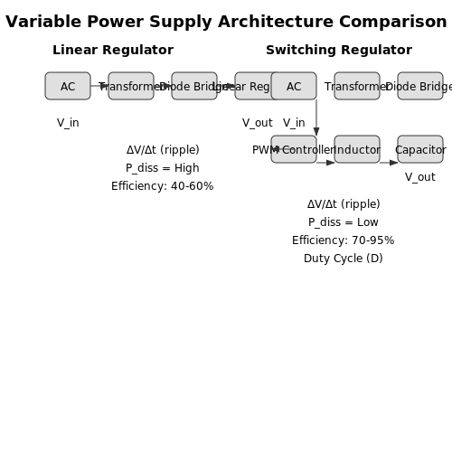
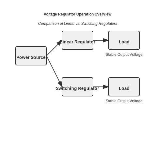
Voltage regulators can be broadly categorized into two types: linear and switching regulators. Linear regulators provide a simple and efficient way to regulate voltage by dissipating excess voltage as heat, whereas switching regulators use a more complex approach that employs inductors and capacitors to regulate output without significant power loss.
- Linear Regulators: These devices maintain a constant output voltage by operating in an active region. Their simplicity and low noise make them popular for applications requiring minimal voltage fluctuation. However, their efficiency can drop significantly under high load or voltage disparities.
- Switching Regulators: Utilizing high-frequency switches, these regulators can transfer energy efficiently without dissipating much heat. They are widely used in applications where power conversion efficiency and compact size are paramount, such as in battery-operated devices.
Importance of Voltage Regulation in Application
Voltage regulation is particularly crucial in various real-world applications, ranging from consumer electronics to industrial automation and renewable energy systems. For instance:
- Consumer Electronics: Devices such as smartphones and laptops require stable voltage to function optimally, preventing malfunction or damage.
- Industrial Automation: In manufacturing systems, voltage regulation ensures that sensors and actuators work reliably, minimizing downtime.
- Renewable Energy Systems: Solar inverters utilize voltage regulation to convert fluctuating DC voltage to a stable AC output, enhancing grid stability.
Factors Affecting Voltage Regulation Performance
The performance of voltage regulators can be influenced by various factors, including:
- Temperature Changes: Variations in temperature may affect the behavior of electronic components, leading to changes in output voltage.
- Load Variations: Rapid changes in load current can result in transient responses, affecting voltage stability.
- Input Voltage Fluctuations: Unstable supply voltage can lead to inadequate regulation, imposing further demands on the regulator.
To mitigate these effects, engineers must consider both the design and operational parameters of voltage regulators tailored to specific applications.
In conclusion, understanding the basic concepts of voltage regulation is fundamental for developing advanced electrical and electronic systems. As we explore more complex applications of applied voltage regulators, the foundational knowledge acquired here will serve as a valuable reference.
2. Linear Voltage Regulators
2.1 Linear Voltage Regulators
Linear voltage regulators are critical components in electronic circuits used to provide a stable output voltage while minimizing voltage ripple, thus ensuring the reliability and performance of various devices. Understanding their principles of operation, design considerations, and real-world applications can significantly enhance the efficiency and reliability of power supply systems.
Basic Principles of Linear Voltage Regulators
Linear regulators operate under the principle of voltage regulation using a series-pass element, typically a transistor, which adjusts its resistance to maintain a constant output voltage despite variations in the load current or input voltage. This mechanism ensures that the output remains stable even in fluctuating conditions, thus making it ideal for sensitive electronics.
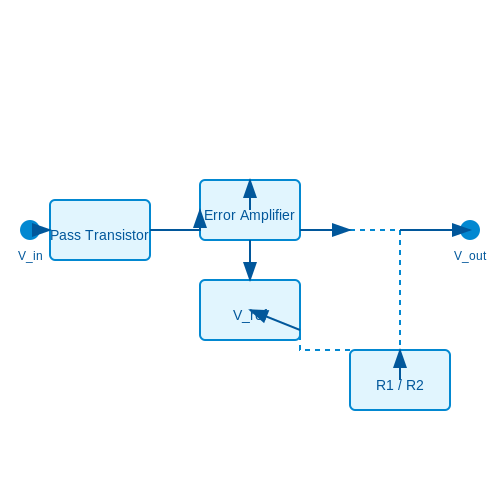
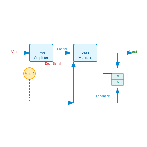
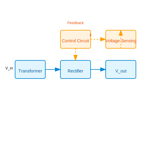
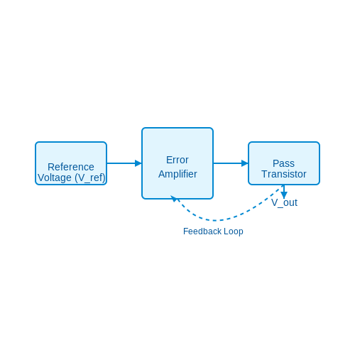
The standard configuration includes three main components: a reference voltage source, an error amplifier, and a pass transistor. The reference voltage establishes the desired output voltage, while the error amplifier compares the output voltage to this reference. If the output voltage deviates from the set point, the error amplifier adjusts the pass transistor accordingly. This feedback loop functions continuously, maintaining regulation with minimal transient response time.
Mathematical Modeling of Linear Voltage Regulators
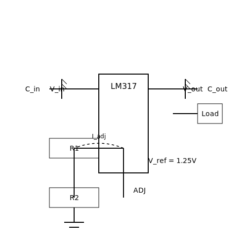
The output voltage (\(V_{out}\)) of a linear voltage regulator can be described with the following relationship:
In this equation, \(V_{ref}\) is the reference voltage, and \(R_1\) and \(R_2\) are the resistances in the feedback network. The feedback network plays an essential role in determining the output voltage, allowing for fine-tuning and optimization based on specific design requirements.
To derive this equation:
- Start with the voltage divider formula, where \(V_{out}\) is dependent on \(V_{ref}\) and the ratio of resistances.
- The current through \(R_1\) is the same as that through \(R_2\) under closed-loop conditions, leading to the aforementioned equation.
Switching Characteristics and Efficiency
While linear regulators can provide high output voltage accuracy, they are not without drawbacks, particularly concerning efficiency. The efficiency (\(\eta\)) of a linear regulator can be computed as:
Where \(V_{in}\) is the input voltage. As shown in this equation, the efficiency improves with a smaller difference between \(V_{in}\) and \(V_{out}\). However, with a significant voltage differential, power loss will occur in the form of heat, necessitating proper thermal management strategies such as heat sinks or thermal pads.
Real-World Applications
Linear voltage regulators are prevalent in a plethora of applications:
- Power supplies for analog devices where low noise is paramount.
- Power management in battery-operated devices where voltage stability is crucial.
- Instrumentation and medical devices where precision is necessary.
Despite the rise of switching regulators—known for their efficiency—linear regulators remain indispensable for applications needing simplicity, low cost, and minimal output noise.
Conclusion
The linear voltage regulator exemplifies the balance between simplicity and effective performance in electronic design. While understanding its underlying principles is essential, its application in various technologies demonstrates its enduring relevance in modern electronics. As one explores more advanced topics in voltage regulation, the next logical step involves diving into switching voltage regulators to appreciate the comparative advantages and challenges they present.
2.1.1 Series Voltage Regulators
In the realm of applied voltage regulators, series voltage regulators hold a prominent position due to their simplicity and effectiveness in maintaining a constant output voltage despite variations in load current and input voltage. This section delves into the operational principles, design considerations, and practical applications of series voltage regulators.
Operational Principles
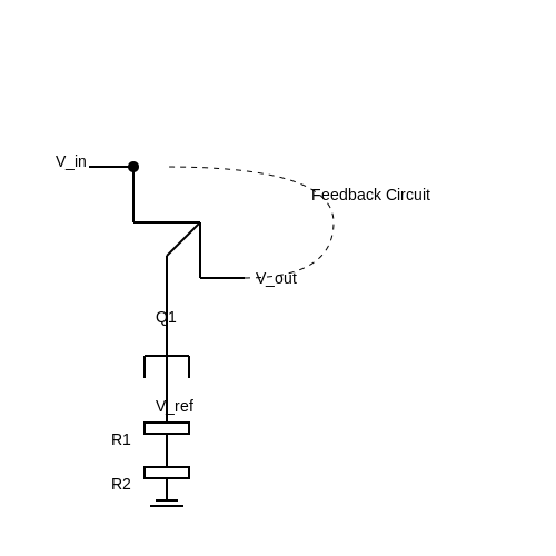
At the heart of a series voltage regulator is a voltage reference and an active component, typically a transistor, that operates in series with the load. The basic functionality hinges on the transistor's ability to adjust its resistive characteristics based on the feedback from the output voltage. When the output voltage dips below a predetermined level, the feedback circuit activates to increase the conduction of the transistor, which compensates for the drop by allowing more current to flow to the load.
Conversely, if the load voltage exceeds the desired output, the feedback mechanism decreases the current flow through the transistor, thus maintaining a stable voltage output. This regulation technique is crucial in applications where supply variations could lead to detrimental effects on sensitive electronic components.
Mathematical Representation
To derive the transfer characteristics of a series voltage regulator, we can start with Kirchhoff's voltage law applied to the circuit, which can typically be represented as:
Where \( V_{in} \) is the input voltage, \( V_{out} \) is the regulated output voltage, and \( V_{CE} \) is the voltage drop across the transistor. Rearranging this gives us:
In practice, the output voltage can be regulated using a feedback mechanism provided by a voltage reference and a control transistor. The feedback network often employs resistors to set the desired output voltage, \( V_{out} \), through the equation:
Here, \( V_{ref} \) represents the reference voltage, while \( R_1 \) and \( R_2 \) form a voltage divider. Controlling the ratio of these resistors helps achieve the desired output voltage while ensuring stable operation.
Design Considerations
When designing a series voltage regulator, several factors must be taken into account:
- Power Dissipation: As the input voltage increases above the output, the excess energy dissipated as heat can lead to thermal failure. Adequate heat sinking must be employed to manage junction temperatures.
- Load Regulation: This indicates how well the output voltage can maintain its set value under varying load conditions. Generally, a lower load regulation is desirable.
- Line Regulation: This measures how much the output voltage changes with variations in the input voltage. It is critical for maintaining steady output during input fluctuations.
- Transient Response: It is vital for the regulator to respond quickly to sudden changes in load conditions to prevent voltage deviation that can affect sensitive circuits.
Applications
Series voltage regulators are extensively used in various applications, particularly where regulated voltage source is required:
- Power Supplies: They are fundamental in linear power supply designs, where they provide a stable output while filtering noise from power supply lines.
- Consumer Electronics: Many personal devices such as smartphones and laptops use series voltage regulation to ensure critical components receive consistent voltage, thus enhancing performance and longevity.
- Communication Equipment: In radio frequency applications, the regulated voltage ensures signal integrity through stable power conditions.
In summary, series voltage regulators are a vital component of modern electronic design, serving to ensure reliability across a broad spectrum of technologies. As devices become more sensitive, the importance of effective voltage regulation only continues to grow.
2.1.2 Shunt Voltage Regulators
Shunt voltage regulators present a fundamental approach to voltage regulation, utilizing the principle of parallel voltage regulation. They are characterized by their ability to maintain a stable output voltage across a load by dissipating excess voltage as heat. This design is particularly simple and cost-effective, making it a favored option in various applications, especially where output currents are moderate.
Operating Principle
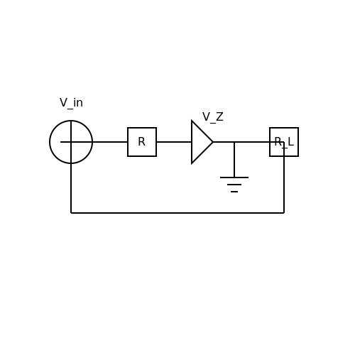
A shunt voltage regulator generally consists of a variable resistance component that is connected in parallel with the load. When the input voltage exceeds a predetermined threshold, the regulator adjusts its resistance to maintain the output voltage at a constant level. The behavior of the shunt voltage regulator can often be illustrated using a simple circuit consisting of a Zener diode and a series resistor.
When using a Zener diode, the device operates in its breakdown region, specifically designed to provide a stable voltage drop across it. This allows for effective control of the voltage supplied to the load:
Here, \( V_Z \) represents the Zener breakdown voltage, which is typically very stable as long as the diode is maintained within its rated current limits.
Basic Circuit Configuration
The basic configuration of a shunt voltage regulator with a Zener diode can be illustrated with a circuit diagram. In this configuration:
- The input voltage \( V_{in} \) is applied across a resistor \( R \) connected in series with the Zener diode.
- The Zener diode is connected in parallel with the output load \( R_L \).
This arrangement leads to effective voltage regulation by allowing the Zener diode to conduct whenever the input voltage exceeds \( V_Z \), redirecting excess current away from the load while maintaining a stable voltage level.
Design Considerations
When designing a shunt voltage regulator, several critical factors must be taken into account:
- Power Dissipation: The power dissipated by the Zener diode increases with the current flowing through it. This can be approximated using the formula:
- Where \( P_Z \) is the power dissipated, \( I_Z \) is the Zener current, and \( V_Z \) is the Zener voltage.
- Current Ratings: It is crucial to ensure that the Zener diode and series resistor can handle the maximum expected current.
- Load Regulation: A shunt regulator's ability to maintain output voltage consistency is influenced by fluctuations in load current. Proper component selection is essential for achieving desired performance.
Applications
Shunt voltage regulators find applications in various scenarios where low power requirements exist, making them suitable for:
- Low Power Supplies: Often utilized in simple low-power power supplies for sensors and microcontrollers.
- Reference Voltage Sources: Can be employed as stable voltage references in sensor applications.
- LED Drivers: Used in LED applications where precise voltage is crucial for consistent brightness.
Conclusion
Shunt voltage regulators offer a straightforward and practical solution to voltage regulation, particularly suitable for applications characterized by moderate currents and voltage levels. By leveraging the properties of components like Zener diodes, circuit designers can achieve reliable voltage control with minimal complexity. Understanding these principles allows engineers to implement effective voltage regulation strategies tailored to their specific requirements.
2.2 Switching Voltage Regulators
Switching voltage regulators represent a vital area of electronic power management, balancing efficiency and performance in diverse applications ranging from consumer electronics to industrial power supplies. Unlike linear regulators that dissipate excess voltage as heat, switching regulators convert input voltage into a different output voltage using techniques that significantly reduce energy waste. This section dives into the principles, types, and applications of switching voltage regulators, along with a breakdown of their operational characteristics.
Operating Principles
Switching voltage regulators operate by rapidly switching the input voltage on and off rather than dissipating power. This is achieved using components such as transistors and inductors. The key to their operation lies in the following two fundamental principles:
- Energy Storage: At a high frequency, the inductor stores energy when the switch (usually a transistor) is closed and releases it to the output when the switch is open.
- Pulse Width Modulation (PWM): The ratio of the time that the switch is on (duty cycle) to the total cycle time determines the average output voltage.
The efficiency of a switching regulator can exceed 90%, making them suitable for high-performance applications where thermal management presents challenges. The switching frequency typically ranges from a few kilohertz to several megahertz, enabling the design of compact filter components.
Types of Switching Voltage Regulators
There are several types of switching voltage regulators, each designed for particular applications and requirements:
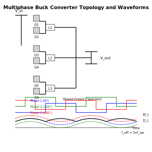
- Buck Converter: This type steps down the input voltage to a lower output voltage. The buck converter can be ideal in battery-powered applications where energy efficiency is critical.
- Boost Converter: A boost converter serves to step up the voltage. It is frequently used in scenarios requiring higher voltage output from a lower voltage supply, such as in portable electronics.
- Buck-Boost Converter: Combining both buck and boost capabilities, this regulator provides versatility to either step up or step down the input voltage based on specific circuit demands.
- Flyback Converter: This is ideal for applications requiring electrical isolation between input and output. Flyback converters are common in low-power applications, such as chargers where secondaries are isolated.
Mathematical Modeling
To understand the efficiency and performance metrics of a switching regulator, it's essential to delve into some mathematics. The basic relationship dictating the duty cycle (D) for a buck converter can be expressed as follows:
Where:
- Vout: Output voltage
- D: Duty cycle, expressed as the ratio of on time to total time
- Vin: Input voltage
For a boost converter, the duty cycle is given by:
Practical Applications
Switching regulators find application in myriad fields due to their efficiency and adaptability. Here are some notable use cases:
- Electronics Power Supply Units: They efficiently supply power to devices by converting various voltage levels. This is critical in devices like smartphones and laptops where size and efficiency are paramount.
- Electric Vehicles: In electric and hybrid vehicles, switching regulators manage battery voltages and optimize energy consumption, contributing to extended vehicle range.
- LED Drivers: Many LED lighting systems use switching regulators to maintain consistent brightness and reduce energy waste.
In conclusion, the versatility and efficiency of switching voltage regulators make them integral to modern electronics. Their ability to manage voltage levels intelligently while minimizing power loss highlights their essential role in varying applications. As technology evolves, these regulators continue to find new frontiers, pushing the limits of power management.
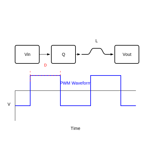
2.2.1 Buck Converters
In the realm of applied voltage regulators, the buck converter stands as one of the most efficient DC-DC converter architectures. It steps down voltage by utilizing a combination of switching elements, energy storage components, and control mechanisms. The fundamental operation of buck converters relies on the principles of energy conservation and inductor-capacitor (LC) dynamics, making it essential to explore both the theoretical framework and practical implementations.
Understanding the Basics of Buck Converters
A typical buck converter circuit consists of a switch, a diode, an inductor, and a capacitor. The switch, often a MOSFET, periodically opens and closes, allowing the input voltage to be transferred to the output in controlled bursts. By adjusting the duty cycle of the switch (the ratio of on-time to the total switching period), the average output voltage can be regulated. This method of voltage regulation is particularly efficient, as the power loss primarily occurs during the switching transitions.
The operation can be visualized as follows: when the switch is closed, current flows through the inductor, storing energy in its magnetic field. Upon opening the switch, the energy stored in the inductor is released through the diode to the load capacitor, which also helps to smooth the output voltage. This process leads to a steady average output voltage that can be tuned by varying the duty cycle.
In this equation, Vout is the output voltage, D is the duty cycle, and Vin is the input voltage. This direct proportionality showcases the fundamental relationship governing buck converters, enabling engineers to calculate expected output voltages accurately.
Operational Principles and Efficiency
The efficiency of a buck converter is affected by several factors, including the quality of the components used, the switching frequency, and the control method implemented. In practical applications, ideal components yield efficiencies between 85% and 95%. However, non-ideal characteristics, such as on-resistance of the switch and forward voltage drop of the diode, can increase power losses.
A common measure of efficiency can be expressed as:
Here, η represents the efficiency, while Iout and Iin denote the output and input current, respectively. The ability to maximize this efficiency plays a significant role in applications ranging from battery-powered devices to industrial power supplies.
Practical Implementation and Real-World Applications
Buck converters find widespread applications due to their high efficiency and compact design. They are commonly used in:
- Battery management systems for efficient power conversion
- Power supplies for microcontrollers and FPGA devices
- DC motor drives requiring a stable and reduced voltage
- Renewable energy systems, such as solar panels, for optimizing output to load demand
Moreover, advancements in semiconductor technology have led to the development of integrated buck converter chipsets that include built-in control algorithms, further simplifying the design process and enhancing performance. Such innovations make buck converters increasingly appealing in modern electronics systems.
In conclusion, buck converters exemplify an effective means of voltage regulation, driven by their operational principles rooted in energy storage and efficient switching. As engineers continue to innovate in design and implementation, buck converters will remain integral to advancing electric power management solutions.
2.2.2 Boost Converters
Boost converters, also known as step-up converters, are a crucial component in power electronics, employed to step up a low input voltage to a higher output voltage. This ability to elevate voltage makes them indispensable in numerous applications, ranging from battery-powered devices requiring higher voltage levels to renewable energy systems that capitalize on fluctuating input voltages. The fundamental operating principle of a boost converter lies in its inductive energy storage mechanism. By utilizing an inductor, a switch (usually a transistor), a diode, and a capacitor, the circuit can convert and increase voltage while maintaining power conservation – a manifestation of the law of conservation of energy. At its core, the process can be understood through the relationship between voltage, current, and the inductor’s stored energy. When the switch is closed, current flows through the inductor, storing energy in the form of a magnetic field. This process is characterized by an upward ramp of current and a corresponding voltage drop across the inductor. The energy stored in the inductor is directly related to the current flowing through it, as described by the equation: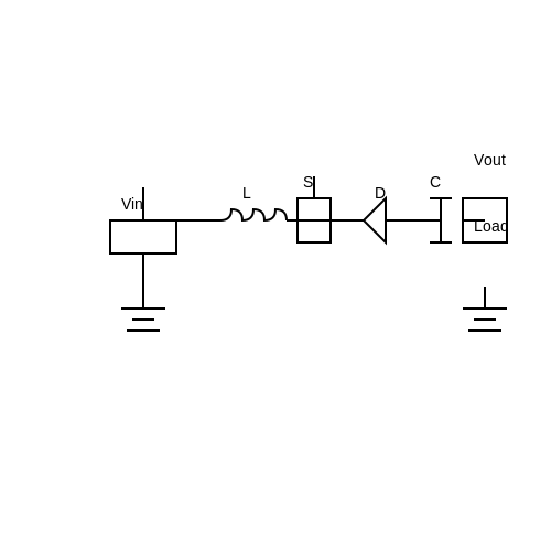
2.2.3 Buck-Boost Converters
The Buck-Boost converter is a versatile power supply topology able to step down or step up an input voltage. This flexibility makes it highly valuable in many applications where the varying nature of power sources creates the need for adaptive voltage regulation. Unlike traditional buck or boost converters, which only serve a single function, the buck-boost converter deftly combines both functionalities into a single device, allowing engineers to efficiently manage power in a wide range of scenarios.
Theoretical Foundation
At the core of the Buck-Boost converter's operation are energy storage elements—typically an inductor and a capacitor—along with a controlled switch, usually a transistor. The operation is based on two primary states: the 'on' state, where the switch allows current to flow through the inductor, and the 'off' state, which releases the energy stored in the inductor to the output circuit. The efficiency and output voltage can be modeled mathematically to ensure optimal performance. By analyzing the voltages and currents at different points, engineers can derive critical relationships.
Mathematical Models
Let's derive the output voltage equation for a Buck-Boost converter. The fundamental principle lies in the conservation of energy, where the energy transferred to the inductor is equal to the energy supplied to the load.
During the 'on' state, the voltage across the inductor \( V_L \) can be expressed as:
In this state, we can write the inductor voltage as:
When the switch is turned off, the voltage across the load becomes:
where \( D \) is the duty cycle. This parameter is critical, as it dictates the ratio of the time the switch is on to the total cycle time. By adjusting \( D \), an engineer can control the output voltage according to application needs, giving the Buck-Boost converter its flexibility.
Waveforms and Control Techniques
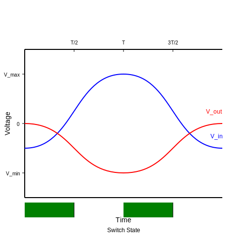
Control techniques used in Buck-Boost converters often involve pulse-width modulation (PWM), which dictates the duty cycle and consequently the output voltage. The resulting waveforms showcase the alternation between the charging and discharging phases of the inductor, yielding an average output voltage that can either be greater than or less than the input voltage.
A typical operational waveform for a Buck-Boost converter will show the input voltage and output voltage over time, illustrating the periodic operation of the switch, which alternates the circuit state.
For practical applications, these converters find wide-ranging uses, especially in battery-powered devices, automotive applications, and renewable energy systems like solar batteries, where battery voltages can fluctuate significantly. There, having a reliable means to either step up or step down voltages ensures operational stability and efficiency.
Efficiency Considerations
Efficiency is paramount in any power electronics design. The efficiency of a Buck-Boost converter can be impacted by several factors, including the quality of components, switching frequency, and thermal management. As power loss reduces overall efficiency, engineers must consider advancing technologies such as synchronous rectification to improve performance. Modern Buck-Boost designs often prioritize minimizing switching losses, optimizing layout designs for thermal management, and selecting high-performance components.
In summary, Buck-Boost converters are essential in, for example, fuel cell applications that require efficient voltage regulation across fluctuating load conditions. Their unique ability to adapt voltage levels helps facilitate energy management in various innovative technologies today, from portable electronics to larger industrial systems.
3. Operation of Linear Regulators
3.1 Operation of Linear Regulators
Linear voltage regulators are fundamental components in electronics, serving to maintain a steady output voltage despite variations in input voltage and load conditions. Their operational principle is grounded in analog electronics, employing passive and active components to achieve voltage regulation with minimal ripple and noise. This section delves into the mechanics of linear regulators, highlighting their underlying principles, typical configurations, and practical applications.
Basic Working Principle
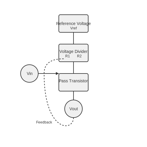
At the heart of a linear regulator lies a feedback loop that continuously monitors the output voltage. The most widely used linear regulator configuration employs a transistor (which serves as a variable resistor) in conjunction with a reference voltage source. The reference voltage sets the desired output voltage by controlling the conduction of the transistor. When the input voltage varies, the feedback mechanism adjusts the resistance of the transistor accordingly, ensuring that the output voltage remains stable.
In a typical setup, the circuit includes:
- A reference voltage source that serves as a stable point against which the output voltage is compared.
- A feedback loop consisting of a voltage divider that senses the output voltage and compares it with the reference voltage.
- A pass transistor, which adjusts its conductivity based on the feedback signal, thereby regulating the output voltage.
Mathematical Derivation of Voltage Regulation
To quantitatively describe how a linear regulator maintains its output voltage, we can start with the fundamental relationship governing the operation of the pass transistor. The output voltage, \( V_{out} \), can be expressed as:
In this equation:
- \( V_{ref} \) is the reference voltage output from the regulator.
- \( R_1 \) and \( R_2 \) are the resistors in the voltage divider that sets the feedback voltage returned to the comparator.
In an ideal scenario, as long as the input voltage \( V_{in} \) remains above the minimum required by the regulator (including the dropout voltage), \( V_{out} \) remains constant. The key factor in a linear regulator's design is the dropout voltage—the minimum difference between \( V_{in} \) and \( V_{out} \) required for the regulator to function effectively. This dropout voltage can vary based on the design and the type of pass transistor used (typically bipolar junction or MOSFET).
Types of Linear Regulators
Linear regulators can be classified into several types based on their design and operational parameters:
- Low-Dropout Regulators (LDOs): These can maintain output voltage with very small input-output voltage differentials, making them suitable for battery-operated devices.
- Adjustable Regulators: These allow the user to set the desired output voltage using external resistors.
- Fixed Voltage Regulators: These provide a predetermined output voltage, commonly used in many consumer electronics.
Practical Applications
Linear regulators find their utility in numerous applications including:
- Power supply circuits in analog devices where low noise is crucial.
- Voltage regulation in power management systems, such as in processors and RF modules.
- Signal conditioning circuits that require stable operation over a range of input conditions.
Due to their simplicity and reliability, linear regulators are often a first choice in designs where power efficiency is not as critical as circuit simplicity and output stability.
In sum, understanding the operation and characteristics of linear regulators is essential for engineers designing robust circuits that require stable voltages. As we progress to more complex voltage regulation methods in the following sections, the foundational knowledge of linear regulators will enhance our understanding of how they integrate into various applications.
3.2 Operation of Switching Regulators
In the landscape of applied voltage regulation, switching regulators stand out for their efficiency and versatility. Unlike linear regulators, which dissipate excess voltage as heat, switching regulators convert input voltage efficiently, making them essential for modern power management in electronic devices. Understanding their operation begins with the two basic modes: Buck (step-down) and Boost (step-up) regulation. Let us delve into the operational principles of switching regulators, highlighting their components and functionality.Basic Operation Principle
At the core of switching regulators is the process of switching energy in and out of an inductor or transformer. This method allows the conversion of voltages with minimal loss. The fundamental operation relies on a control mechanism to adjust the duty cycle of the switching element—typically a transistor. When the switch is on, current flows through the inductor, storing energy in its magnetic field. When the switch turns off, the inductor releases energy to the output capacitor and load. This interplay results in a well-regulated output voltage despite fluctuations in the input voltage or load conditions. To illustrate this process, consider the Buck converter. The circuit includes a switch, an inductor, a diode, and a capacitor. When the switch is closed (ON state), the voltage across the inductor increases, and energy is stored. When opened (OFF state), the inductor discharges through the load via the diode, maintaining the output voltage.Mathematical Analysis of Switching Regulators
To analyze a Buck converter mathematically, we derive the relationship between input voltage \( V_{in} \), output voltage \( V_{out} \), and duty cycle \( D \). 1. Energy conservation principles apply: When in the ON state: - The voltage across the inductor \( V_L = V_{in} - V_{out} \) - The current change in the inductor \( I_L \) can be expressed as: $$ \Delta I_L = \frac{V_L \cdot D}{L} \cdot T $$ where \( L \) is the inductance and \( T \) is the switching period. 2. Average output voltage calculation can be derived: - The average output voltage over a complete switching cycle is given by: $$ V_{out} = D \cdot V_{in} $$ This shows a linear relationship between the input and output voltages, revealing the potential for significant voltage regulation with appropriate duty cycle control. 3. Output voltage ripple depends on inductor values and load characteristics: The ripple voltage \( \Delta V_{out} \) can be expressed as: $$ \Delta V_{out} = \frac{I_{out} \cdot T}{C} $$ where \( C \) is the output capacitance. By adjusting the duty cycle \( D \), designers can fine-tune the output voltage to meet specific requirements, thereby enhancing system stability and efficiency.Practical Applications
Switching regulators are ubiquitous in power supply design, serving a wide range of applications including: - Battery-powered devices: They efficiently convert battery voltage to required levels while maximizing battery life. - Power management in microcontrollers: Switching regulators provide a stable voltage supply necessary for sensitive electronic components that can operate at lower voltage levels. - Photovoltaic systems: They optimize energy harvested from solar panels, facilitating maximum power point tracking (MPPT) to enhance performance under variable lighting conditions. Furthermore, the advent of integrated switching regulators has simplified design processes, allowing engineers to deploy compact and highly efficient power solutions in consumer electronics, automotive systems, and even high-performance industrial applications. With an understanding of the operational principles and their practical significance, designers can leverage the capabilities of switching regulators, leading to innovative solutions in power management—critical in today’s tech-driven world.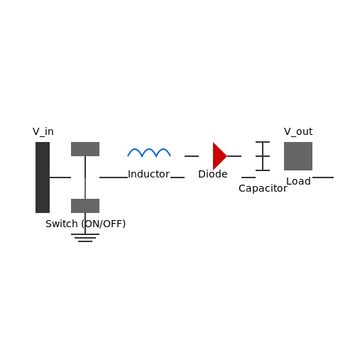
3.2.1 Control Methods
In the realm of applied voltage regulators, the efficiency and stability of power supply systems significantly depend on the chosen control methods. Understanding these methods enables engineers and researchers to devise solutions tailored for various applications, ranging from battery chargers to sophisticated renewable energy systems. The control methods broadly fall into two categories: linear regulation and switching regulation. Each method employs different mechanisms to maintain a consistent output voltage in response to variations in input voltage or load current, yet they cater to distinct operational environments and requirements.Linear Regulation
Linear regulators operate on the principle of maintaining a constant output voltage by sacrificing some input voltage as heat. They often utilize a series pass transistor, which adjusts its resistance to vary the voltage drop according to the feedback received from the output. This feedback loop ensures that, regardless of load changes, the output remains stable. The fundamental equation governing the relationship in a linear regulator can be understood through Kirchhoff's Voltage Law (KVL):Switching Regulation
Switching regulators, on the other hand, achieve regulation by rapidly toggling a transistor on and off, storing energy in inductors or capacitors, thereby stepping down or stepping up the voltage with minimal energy loss. This method excels in preserving power efficiency and generating less heat, making it suitable for portable and high-power applications. The basic operation involves understanding the duty cycle, defined as the ratio of the "on" time to the total cycle time:Practical Applications and Considerations
The choice between linear and switching regulation methods hinges on various factors including efficiency, cost, complexity, and thermal management. In applications where simplicity is paramount and power loss can be tolerated, linear regulators may be preferred. In contrast, for power-sensitive applications that demand high efficiency and lower heat output, switching regulators are often the solution of choice. Moreover, recent advancements in control techniques, such as pulse-width modulation (PWM) and voltage-mode control versus current-mode control, have further optimized the performance of both linear and switching voltage regulators, adapting them for sophisticated applications that require precision and reliability. In summary, the understanding of control methods in applied voltage regulators is crucial for the design and implementation of effective power supply systems. By weighing the trade-offs and benefits of each method, engineers and researchers can tailor voltage regulation strategies that meet the demands of their specific applications.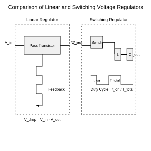
3.2.2 Feedback Mechanisms
In the realm of applied voltage regulators, feedback mechanisms are pivotal for achieving stability and precision in output voltage regulation. These analog control systems rely on continuous monitoring and adjustment to ensure that output voltage remains constant regardless of variations in load or input voltage. Understanding feedback mechanisms helps engineers design more reliable and responsive electronic systems. Feedback can be categorized into two main types: negative feedback and positive feedback. Negative feedback, the more common form in voltage regulation, aims to reduce discrepancies between the output voltage and the desired reference voltage. When the output voltage dips below the setpoint, negative feedback mechanisms increase the output; conversely, if the output rises above the reference, the mechanism decreases output. This dynamic balance is essential for maintaining stability in the system. In voltage regulators, a typical feedback loop involves several key components: a reference voltage source, an error amplifier, and a pass element, such as a transistor. The feedback process begins with the error amplifier comparing the output voltage to a stable reference voltage. This comparison generates an error signal, proportional to the deviation of the output voltage from the reference. The error signal is then processed, often amplified, and used to adjust the operation of the pass element that controls the output voltage. To understand the mathematical underpinnings of this process, let’s derive the relationship governing a simple linear voltage regulator with negative feedback. The standard feedback formula can be expressed as: $$ V_{out} = V_{ref} \cdot (1 + \frac{R_f}{R_i}) $$ In this equation, \(V_{out}\) is the regulated output voltage, \(V_{ref}\) is the reference voltage from the error amplifier, \(R_f\) is the feedback resistor connected to the output, and \(R_i\) is the resistor connected to ground. By manipulating the resistors \(R_f\) and \(R_i\), designers can determine the desired output voltage with precise control over the feedback loop. To delve further into the dynamics of the feedback loop, let’s analyze the transfer function, which describes how the output responds to changes in input. The transfer function \(H(s)\) of the feedback system can be derived from the standard second-order linear system response: $$ H(s) = \frac{K}{s^2 + \frac{\omega_n}{Q}s + \omega_n^2} $$ Here, \(K\) represents the system gain, \(\omega_n\) is the natural frequency, and \(Q\) is the quality factor. By analyzing this transfer function, engineers can assess system stability and design compensators as needed to enhance performance. One practical application of feedback mechanisms in voltage regulation can be seen in modern switching regulators. These devices utilize pulse-width modulation (PWM) techniques and often incorporate advanced feedback algorithms to achieve high efficiency. By adjusting the duty cycle of the PWM signal, the output voltage can be maintained at a desired level while optimizing power consumption. Another important aspect of feedback mechanisms in voltage regulators is their impact on transient response. The speed and accuracy of the feedback loop significantly influence how well the regulator can handle sudden changes in load current. For example, a well-designed feedback mechanism allows for minimal voltage droop or overshoot during rapid load transients, thereby enhancing the overall reliability of the power supply in critical applications, such as in telecommunications and computing systems. In conclusion, feedback mechanisms form the backbone of effective voltage regulation systems. By understanding the intricacies of negative and positive feedback, along with their practical implications and mathematical foundations, engineers can design advanced circuits that not only stabilize output voltage but also respond adeptly to ever-changing demands in real-time situations. Through careful tuning and implementation, these feedback systems ultimately contribute to the longevity and efficiency of electronic devices across various industries.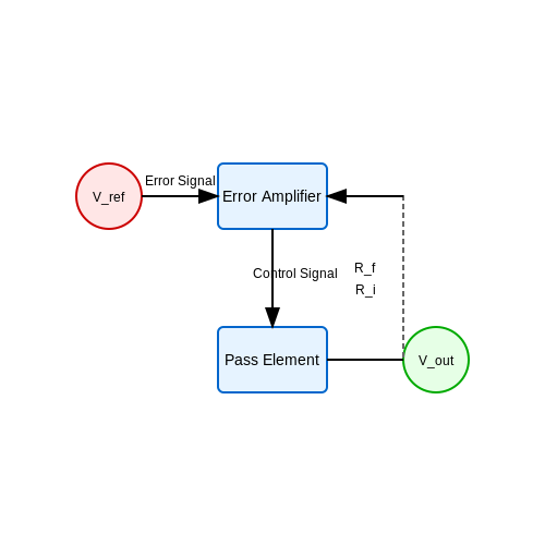
4. Consumer Electronics
4.1 Consumer Electronics
In the realm of consumer electronics, voltage regulators play a pivotal role in ensuring devices operate within their specified voltage ranges, protecting sensitive components and enhancing performance. As technology evolves, the demand for high-efficiency, compact voltage regulation solutions has increased, leading to significant innovations in this field.
At the core of voltage regulation are two main types: linear and switching voltage regulators. Linear regulators provide a stable output voltage by dissipating excess voltage as heat, making them suitable for low-noise applications where minimal electrical interference is crucial. In contrast, switching regulators utilize an on-off switching mechanism, allowing for higher efficiency by reducing energy loss, making them ideal for portable devices such as smartphones and laptops.
Linear Voltage Regulators
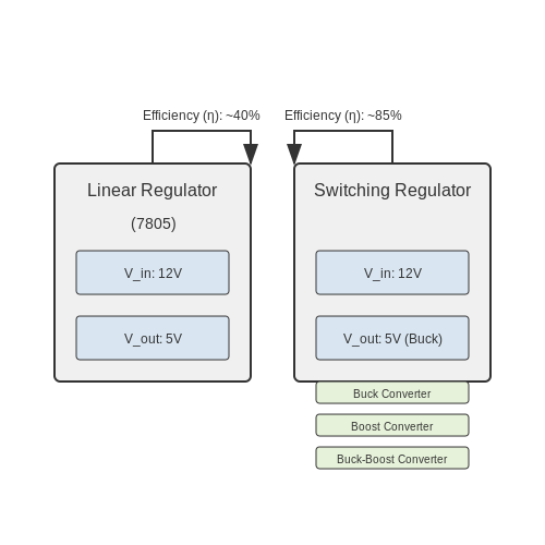
Linear regulators are often chosen for their simplicity and low cost. The basic operation of a linear regulator relies on a control mechanism that maintains a constant output voltage despite variations in input voltage and load current. For example, a common linear regulator is the 7805, which outputs a fixed 5V. The power dissipation (PD) can be calculated using the formula:
Here, Vin is the input voltage, Vout is the desired output voltage (5V in this instance), and Iload is the current being supplied to the load. This formula highlights the trade-offs when using linear regulators — as input voltage increases or output current demand rises, power dissipation increases, leading to potential thermal issues.
Switching Voltage Regulators
Switching regulators use inductive storage elements to convert and regulate voltage efficiently. Unlike linear regulators, they can boost or buck (step down) the voltage and are often designed in configurations such as buck, boost, or buck-boost converters. These configurations enable designers to select an appropriate topology based on the specific application requirements. The efficiency (η) of a switching regulator is typically much higher, often exceeding 85%, due to the reduced heat generation.
For instance, the efficiency of a buck converter can be expressed as:
Where Pout is the output power and Pin is the input power. This high efficiency makes switching regulators preferable in battery-operated devices, extending their operational life and minimizing heat issues.
Applications in Consumer Electronics
Modern consumer electronics heavily rely on a variety of voltage regulation techniques. Smartphones, laptops, and tablets often incorporate integrated circuit (IC) voltage regulators to fulfill the power demands of increasingly sophisticated processors and sensors. Power management ICs (PMICs) combine multiple voltage regulation functions in a single chip, optimizing space and efficiency in design.
Another noteworthy development is the trend toward adjustable voltage regulators, which allow device manufacturers to configure output voltages dynamically based on operational requirements. This adaptability is particularly important in applications such as portable media players and e-readers, where battery life is critical.
As manufacturers pursue miniaturization and energy efficiency, understanding the ins and outs of applied voltage regulation becomes increasingly important for engineers and researchers in the consumer electronics sector. New materials, such as wide bandgap semiconductors, are beginning to play a significant role in enhancing the performance of voltage regulators, allowing for smaller device footprints and improved thermal management.
4.2 Industrial Applications
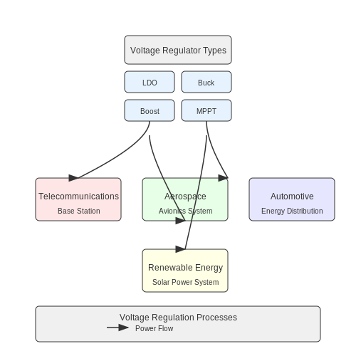
In the realm of engineering and industrial design, applied voltage regulators represent a cornerstone technology pivotal for enhancing operational efficiency, reliability, and safety across a multitude of applications. Working to maintain a set output voltage regardless of variation in input voltage or load conditions, these regulators find essential roles in industries such as telecommunications, aerospace, automotive, and renewable energy sectors. One significant use of voltage regulators is found within power supply systems. For instance, in telecommunications, consistent voltage is crucial for maintaining signal integrity and minimizing data loss. Voltage regulators are integrated into base stations to stabilize the supply voltage, which in turn supports the reliable operation of signal processing equipment. This technological requirement ensures less downtime and enhanced data transmission rates, demonstrating how voltage regulation directly impacts business productivity and user experience. In aerospace applications, where operational environments can be extreme and variable, applied voltage regulators are indispensable. They are employed in aircraft avionics systems to protect sensitive electronics from voltage fluctuations, ensuring the safety and functionality of navigation and control systems. For example, linear voltage regulators (LDOs) are often used in these situations due to their simplicity and low noise characteristics, providing clean and stable voltage to critical systems. Moreover, the automotive industry benefits extensively from voltage regulation technologies, especially with the growth of electric and hybrid vehicles. Here, converters and regulators manage the energy distribution from batteries to motors and other devices. Buck and boost converters play a crucial role in this setting, converting and regulating voltage levels to enhance battery life and efficiency, resulting in better vehicle performance and durability. The integration of renewable energy systems has also underscored the importance of voltage regulators. In solar power installations, for example, maximum power point tracking (MPPT) algorithms often rely on effective voltage regulation to maximize energy extraction from photovoltaic panels. These systems employ complex regulation techniques to ensure that varying input voltage levels from solar panels are converted into a constant voltage output suitable for charging batteries or feeding grid systems. One cannot overlook the historical context of voltage regulators in industrial applications. Since the advent of electronic technologies, devices such as Zener diodes and voltage reference circuits have evolved to provide the necessary regulation. Modern advancements have led to the development of sophisticated digital voltage regulators, which allow for programmable output voltages and real-time feedback control systems. These innovations pave the way for smart grid technologies and further automation in industrial operations. In conclusion, the application of voltage regulators across various industrial sectors exemplifies their essential role in ensuring reliability, safety, and efficiency. By adapting to specific operational demands, these regulators not only enhance system performance but also enable innovations in emerging technologies. Understanding the principles and applications of voltage regulation empowers engineers and researchers to design more robust systems that can meet the challenges of a rapidly evolving technological landscape.Key Takeaways:
- Telecommunications: Voltage regulators maintain signal integrity and system reliability.
- Aerospace: Protect sensitive electronics by stabilizing voltage in extreme conditions.
- Automotive: Manage energy distribution in electric and hybrid vehicles.
- Renewable Energy: Utilize in solar systems for effective energy regulation.
4.3 Automotive Applications
In the automotive industry, the need for reliable voltage regulation is paramount, primarily due to the diverse electrical loads that a vehicle’s system must manage. Modern cars are increasingly reliant on electronic systems for various functions, from basic engine operation to advanced driver assistance systems (ADAS). This subsection delves into the critical role of applied voltage regulators in automotive applications, analyzing their operational requirements, types, and implications for vehicle performance and reliability.
Importance of Voltage Regulation in Automotive Systems
Automotive voltage regulators ensure that electrical systems receive a consistent voltage level, typically around 13.8 to 14.4 volts while the engine is running. This ensures optimal performance across various vehicle components, including:
- Engine Control Units (ECUs): Critical for managing engine efficiency and emissions.
- Safety Systems: Such as airbags and anti-lock braking systems that require precise voltage to function reliably.
- Infotainment Systems: Increasingly complex, they demand stable power supplies for touchscreen interfaces and connectivity.
The shifting demands of automotive power loads necessitate that voltage regulators be both robust and adaptable. This complexity is compounded by the harsh environment found within most automotive applications—from extreme temperatures to vibrations and electromagnetic interference.
Types of Voltage Regulators in Automotive Applications
Generally, two main categories of voltage regulators are utilized in automotive applications: linear regulators and switching regulators. Each type has unique advantages and challenges.
Linear Regulators
Linear voltage regulators are straightforward devices that provide a stable output voltage by dissipating excess voltage as heat. Although they have lower efficiency compared to switching regulators, their simplicity makes them suitable for low-current applications. For instance, linear regulators are often used to power sensitive components, such as microcontrollers and sensor circuits, where low noise is critical.
Switching Regulators
Switching voltage regulators, on the other hand, use inductive and capacitive components to convert one voltage level to another more efficiently. They can achieve efficiencies above 90%, making them ideal for high-current applications, such as battery management systems. The trade-off, however, involves more complexity and potential electromagnetic interference, which necessitates careful design considerations.
If we consider an example application involving a switching regulator, one must understand the basic functional principles:
- The buck converter is designed to step down voltage, using a switch that periodically connects and disconnects the input voltage. This action results in an average output voltage that is lower than the input voltage.
- The boost converter, conversely, increases the voltage and works on a similar principle but in reverse, storing energy in an inductor and releasing it to the output at a higher voltage.
Voltage Regulation and Power Management in Electric Vehicles
Electric and hybrid vehicles present additional complexities with respect to voltage regulation. These vehicles utilize high-voltage batteries (over 300 volts) to manage electric traction motors that power the vehicle. Thus, voltage regulation systems in EVs must effectively manage not only the operational demands of the vehicle but also the charging requirements of the battery systems.
To achieve this, advanced voltage regulation techniques are employed:
- Bidirectional DC-DC converters are often employed to control the flow of power during both charging and discharging of the battery, maintaining stable voltages across the electric drive system.
- Battery Management Systems (BMS) integrate voltage regulation with thermal management and state-of-charge (SoC) monitoring, ensuring safety and efficiency.
The synergy of these advancements leads to improved range, efficiency, and safety in electric vehicles, significantly influencing customer satisfaction and the commercial success of manufacturers.
Conclusion
As automobiles continue to evolve towards greater electronic dependence, the significance of robust voltage regulators cannot be overstated. A thorough understanding of both linear and switching regulators, coupled with advancements in power management strategies, will be paramount for engineers involved in automotive design. The intersection of voltage regulation with emerging technologies will pave the way for the next generation of automotive innovations.
5. Choosing the Right Voltage Regulator
5.1 Choosing the Right Voltage Regulator
When tasked with selecting an appropriate voltage regulator, a myriad of factors influences the decision-making process, from circuit complexity to specific application requirements. Given the pivotal role that voltage regulators play in ensuring system stability and functionality, an advanced understanding of how to navigate this selection is essential.Understanding Voltage Regulator Types
Voltage regulators predominantly fall into two categories: linear and switching.- Linear Regulators: These devices are characterized by their simplicity and low output noise. They regulate output voltage by dissipating excess voltage as heat. While their efficiency is lower compared to switching regulators, they are often preferred in applications where noise is a critical factor, such as in precision analog circuits.
- Switching Regulators: In contrast, switching regulators convert input voltage into a desired output voltage using high-frequency switching techniques. They are known for higher efficiency, particularly for large voltage drops, making them ideal for battery-powered applications where conserving energy is paramount. However, the increased complexity can introduce electromagnetic interference (EMI), which must be managed appropriately.
Key Parameters to Consider
When selecting a voltage regulator, the following parameters should be meticulously evaluated:- Output Voltage and Current Requirements: Understand the specific voltage levels and current demands of your application. It's essential to ensure that the chosen regulator can meet these specifications under all operational conditions.
- Input Voltage Range: The input voltage should always exceed the output voltage by a sufficient margin. For linear regulators, this is commonly called the dropout voltage. For switching regulators, input voltage should encompass expected variations in supply.
-
Efficiency: Calculate the efficiency of the regulator, a critical factor that affects thermal performance and battery life in portable devices. Efficiency (\( \eta \)) can be defined by the equation:
$$ \eta = \frac{P_{out}}{P_{in}} \times 100 $$where \( P_{out} \) is the output power and \( P_{in} \) is the input power.
- Thermal Performance: Analyze the thermal characteristics, including maximum junction temperature, thermal resistance, and the need for heat sinking. This is particularly crucial in linear regulators, where dissipated power directly translates to heat.
- Transient Response: Evaluate the regulator’s ability to respond to rapid changes in load current. This metric is often critical in digital circuits where load conditions fluctuate sharply.
- Noise Performance: For applications in sensitive environments, such as RF circuits or precision analog, it’s crucial to measure and compare the output noise characteristics of different regulators.
Real-World Applications
Understanding these factors can be pivotal as you navigate various applications: - Linear Regulators are widely used in low-noise analog applications, such as audio equipment, where minimal noise and ripple are necessary. - Switching Regulators serve efficiently in modern power supply designs, from automotive electronics that demand robust voltage regulation to solar battery chargers that require adaptable operating parameters. Ultimately, the task of choosing the right voltage regulator is not merely a matter of selecting a component off the shelf; it involves a careful assessment of the operational environment, expected load conditions, and performance expectations. By applying these principles and considering the contextual demands of your specific application, you can streamline the process of voltage regulator selection and ensure a successful design outcome.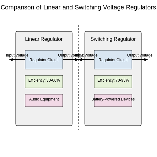
5.2 Thermal Management
Thermal management is a crucial aspect of applied voltage regulators, particularly in the context of power electronics. Voltage regulators, whether linear or switching, generate heat due to power dissipation during operation. Managing this heat is essential not only for maintaining performance but also for ensuring reliability and longevity of the electronic components.
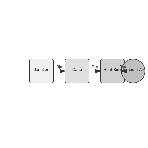
To understand the importance of thermal management, it is necessary to consider the thermal resistance of the system. Thermal resistance is defined as the temperature rise per unit power dissipated and is typically denoted in degrees Celsius per watt (°C/W). In practical terms, it can be viewed as how effectively a system can disperse the heat generated from voltage regulation processes.
Sources of Heat in Voltage Regulators
The primary sources of heat in voltage regulators include:
- Switching Losses: In switching regulators, the transitions between on and off states lead to lost energy, which is converted into heat.
- Conduction Losses: This occurs in both linear and switching regulators and results from the current flowing through resistive components.
- Gate Drive Losses: Especially relevant in switching regulators, this loss is associated with driving the gates of transistors into saturation or cutoff.
Mitigating these sources of heat is paramount when designing voltage regulators. The major approaches to thermal management encompass:
Thermal Solutions
Key thermal solutions are employed to enhance heat dissipation:
- Heat Sinks: A common and effective method involves attaching heat sinks to dissipate heat. The size and design of the heat sink are critical to ensure sufficient thermal contact and surface area for heat transfer.
- Thermal Pads and Greases: These materials improve thermal contact resistance between components and heat sinks by filling microscopic gaps.
- Active Cooling: In high-performance scenarios, active cooling solutions like fans or liquid cooling systems may be necessary to maintain thermal stability.
Calculating Thermal Resistance
To design an effective thermal management strategy, engineers must calculate the thermal resistance from the junction of the semiconductor device to the ambient air. The thermal resistance can be expressed as:
Where:
- Rjc: Junction-to-case thermal resistance
- Rcs: Case-to-sink thermal resistance
- Rsa: Sink-to-ambient thermal resistance
By minimizing these resistance values, engineers can significantly lower the operating temperature of the voltage regulator, which enhances both performance and reliability.
Practical Considerations
In real-world applications, advanced voltage regulators often operate in environments where thermal management becomes even more critical, such as automotive or aerospace systems where space is limited, and the ambient temperatures may vary greatly. Hence, employing computational thermal modeling tools can assist engineers in predicting thermal behavior and optimizing design parameters.
In summary, thermal management is an integral part of designing voltage regulators. It ensures the longevity and reliability of electronic systems in various applications, highlighting the necessity for engineers to incorporate thermal considerations into their designs from the ground up.
5.3 Component Selection
The selection of components in the design of applied voltage regulators is a critical process that directly influences performance, efficiency, and stability. Understanding each component's specifications, characteristics, and the roles they play within the circuit is essential for proficient design and implementation. Let's delve deeper into the essential parameters and considerations that guide proficient engineers in this selection process.Key Components of Voltage Regulators
At the heart of any voltage regulator circuit are several core components:- Voltage Regulator IC: Central component that stabilizes output voltage. Choice between linear or switching types alters performance balance between efficiency and noise.
- Input/Output Capacitors: Ensure stable voltage and filter high-frequency noise. Important aspects include capacitance value, voltage rating, and Equivalent Series Resistance (ESR).
- Resistors: Used for setting output voltage values in adjustable regulators. Tolerance and temperature coefficient are crucial for maintaining voltage accuracy.
- Inductors (in switching designs): Key to energy storage and management, influencing ripple and efficiency. Selection depends on saturation current and DC resistance.
- Diodes: Provide reverse polarity protection and serve as freewheeling components in switching designs. Forward voltage drop and recovery time are vital metrics.
Voltage Regulator Types and Component Variations
Voltage regulators typically fall in the categories of linear regulators or switch-mode power supplies (SMPS). Linear regulators present a simpler design with lower noise but exhibit less efficiency, particularly under significant voltage dropout conditions. When selecting components for linear regulators, prioritize low-dropout (LDO) characteristics if the input voltage is only slightly higher than the output voltage. Moreover, select components with proper thermal characteristics and ensure sufficient derating under load. Conversely, switching regulators are designed to be more efficient, especially in higher power applications. Component selection here includes: - Feedback Capacitors: Essential for stabilizing the output voltage loop. Choose based on stability criteria and the desired bandwidth of the control loop. - Switching Frequency: Must be considered to minimize losses and optimize size. Higher frequencies allow for smaller inductors and capacitors, albeit at the risk of higher switching losses. The selection of parallel input/output capacitors is critical to ensuring effective noise filtering and transient response, which can vary significantly based on load conditions.Importance of Thermal Management
The thermal performance of a voltage regulator is highly influenced by the chosen components. For linear regulators, excessive heat generation may occur under higher loads, necessitating components with robust thermal characteristics and adequate heat sinking. In switching regulators, maintaining the Operating Junction Temperature (OJT) within specified limits is key, as excessive temperatures can influence the reliability and lifespan of electronic components. To effectively manage thermal conditions, consider the power dissipation, given by:Practical Applications and Case Studies
The principles of component selection extend beyond theoretical concepts into various applications, from consumer electronics to industrial automation. An illustrative case involves the design of a compact, efficient power supply for a digital signal processor (DSP) used in audio processing. In this scenario, a high-frequency switching regulator was selected to ensure optimal efficiency and minimal electromagnetic interference (EMI). A comprehensive analysis of component specifications, including selecting low-ESR capacitors and proper inductor for minimal core losses, led to real-world efficiency improvements of 90% or higher. By observing careful design principles in component selection, the resultant system not only achieved operational stability but also met stringent performance criteria within specified thermal limits. ### Conclusion In summary, selecting components for applied voltage regulators necessitates a holistic understanding of electronic component behavior, thermal dynamics, and the specific application requirements. By emphasizing the relationships among components and their effects on the overall performance, engineers can design robust voltage regulation systems that stand up to real-world demands.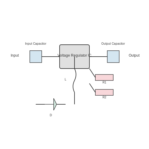
6. Common Issues with Voltage Regulators
6.1 Common Issues with Voltage Regulators
Voltage regulators are critical components in various electronic systems, ensuring that the voltages supplied to circuits remain stable despite variations in input voltage and load conditions. However, several challenges can undermine their efficacy. In this section, we will explore some of the most common issues faced during the application of voltage regulators, emphasizing their underlying mechanisms and practical implications.
Output Voltage Drift
One of the most prevalent issues with voltage regulators is output voltage drift. This phenomenon can occur due to temperature variations affecting the internal components of the regulator. As temperature increases, the resistance of semiconductor materials may vary, leading to deviations in the output voltage. This drift can be particularly problematic in precision applications such as reference voltage sources or sensitive sensor circuits. Monitoring temperature and utilizing temperature compensation techniques, such as thermistors, can help mitigate this issue.
Load Regulation Challenges
Load regulation refers to the ability of a voltage regulator to maintain a constant output voltage as the load current varies. A poorly designed voltage regulator might exhibit significant voltage fluctuations under changing load conditions, leading to insufficient power supply for connected components. This issue can manifest in increased ripple voltage or reduced response time to load transients. Engineers can improve load regulation by incorporating feedback loops in their designs that adjust the output in real-time, ensuring stability. Additionally, using capacitors at the output can help buffer against rapid load demands.
Line Regulation Issues
Line regulation is another critical concern, which focuses on how effectively a regulator maintains output voltage as the input voltage fluctuates. Variations in input voltage, stemming from power supply variations or external disturbances, can result in output voltage variations if not properly managed. This is especially relevant in battery-powered devices where input voltage is often variable. To enhance line regulation, engineers can design voltage regulators with higher loop gain and optimized feedback networks, thereby stabilizing the output against line voltage changes.
Thermal Management
Voltage regulators can dissipate significant amounts of heat, particularly linear regulators that operate by dropping excess voltage. Excessive heat generation can lead to thermal runaway, a condition where increasing temperatures cause a regulator to further increase output current—ultimately damaging components. Effective cooling mechanisms, such as heat sinks or forced air cooling, are necessary to ensure longevity and reliability. For applications where high power loss is expected, switching regulators may be a better choice due to their higher efficiency and lower heat generation.
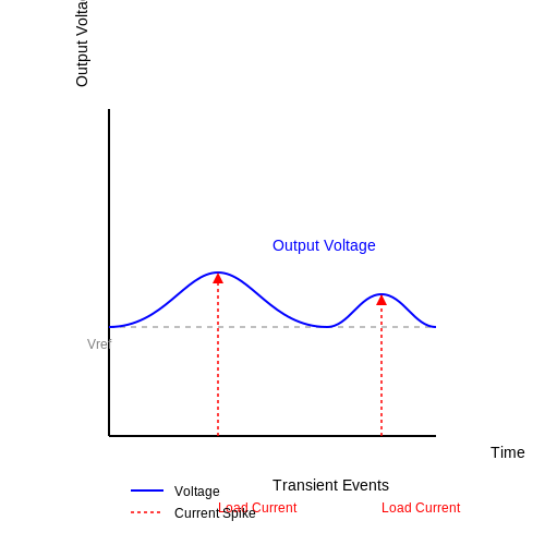
Transient Response
The transient response of a regulator refers to how quickly it can respond to sudden changes in load or input conditions. This response time is critical in applications such as microprocessors, where quick voltage stabilization is essential to avoid performance issues or system crashes. Designers can optimize transient response through appropriate compensating networks and by selecting output capacitors with suitable equivalent series resistance (ESR). Low-ESR capacitors tend to perform better in handling transient loads.
Noise and Ripple
Finally, voltage regulators are not immune to noise and ripple that can affect the integrity of power delivery, particularly in analog and RF applications. Noise in the output can arise from switching events in the regulator or external interference. To combat ripple voltage, proper filtering techniques using capacitors and inductors are recommended. Additionally, shielding the input/output paths can help to minimize the noise picked up from nearby components.
In conclusion, while voltage regulators play a vital role in electronic systems, understanding their common issues allows engineers to design better solutions. By addressing problems such as voltage drift, load and line regulation, thermal management, transient response, and noise, we can ensure that voltage regulators perform optimally, enhancing the overall reliability and stability of electronic circuits.
6.2 Testing Techniques
Testing voltage regulators is a critical procedure that ensures both their functionality and reliability in various applications, from consumer electronics to industrial power systems. Different methodologies can be adopted, depending on the specific desired outcomes, the nature of the circuit, and the required precision. In this section, we will explore several advanced testing techniques pertinent to applied voltage regulators, emphasizing their practical relevance.
Characteristics of Voltage Regulators
A fundamental aspect of testing voltage regulators involves evaluating several key characteristics:
- Load Regulation: Measures the ability of the regulator to maintain output voltage despite variations in load current.
- Line Regulation: Assesses how well the output voltage remains stable with changes in the input voltage.
- Transient Response: Gauges the regulator's ability to respond to sudden changes in load conditions, crucial for applications requiring dynamic response.
- Efficiency: Calculated by the ratio of output power to input power, it determines operational feasibility, especially in battery-powered devices.
Testing Setup and Equipment
To accurately measure these characteristics, a well-designed testing setup is essential. Key equipment typically includes:
- Multimeter: For measuring DC voltage and current.
- Oscilloscope: To visualize the output waveform, especially useful for transient response tests.
- Electronic Load: Simulates various load conditions to assess load regulation and transient response.
- Power Analyzer: To determine efficiency and provide comprehensive datasets on power consumption.
Another useful tool is a programmable power supply, which allows for precise control over input voltage and current, facilitating thorough testing at various operational conditions.
Load Regulation Testing
Begin load regulation tests by setting up the regulator to a specified input voltage while varying the load. The output voltage should remain constant; however, fluctuations may occur due to the design limitations. To derive load regulation quantitatively, we use the following formula:
Perform this measurement at several load points to visualize the load regulation curve. Plotting these points illustrates the regulator's stability under dynamic loads.
Line Regulation Testing
During line regulation testing, the input voltage is incrementally varied while monitoring the output voltage. The objective is to determine the degree to which changes in input voltage affect output voltage. The formula for line regulation is:
Again, this measurement should be performed over a range of input voltages, ensuring a thorough evaluation of performance across expected operational conditions.
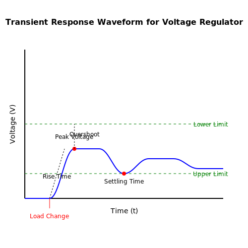
Transient Response Testing
Transient response can be evaluated by applying a step load change and observing how quickly and accurately the output voltage stabilizes. Using an oscilloscope, capture the output waveform and analyze its rise time, overshoot, settling time, and any oscillations. During this test, it is vital to ensure that the output voltage does not exceed specified limits to avoid damaging downstream components.
Efficiency Measurement
Finally, measuring efficiency provides insight into the regulator's performance under load. Efficiency can be derived from the input and output power values:
Where \(P_{\text{out}} = V_{\text{out}} \times I_{\text{out}}\) and \(P_{\text{in}} = V_{\text{in}} \times I_{\text{in}}\). By measuring the output power against the input power, engineers can identify performance bottlenecks.
In conclusion, applying systematic testing techniques can significantly improve the reliability of voltage regulators in real-world applications. Shifting from simple qualitative assessments to rigorous, quantitative evaluations provides a deeper understanding of component behavior, ultimately reflecting in enhanced design precision and durability.
6.3 Diagnostic Tools
In the realm of applied voltage regulators, effective diagnostics play a pivotal role. Understanding the operational behavior of these devices is crucial for ensuring optimal performance and reliability. Various tools exist for diagnosing issues in voltage regulation systems, ranging from basic multimeters to complex analytical instrumentation.
Measurement Tools
The foundation of any diagnostic process begins with measurement tools. Multimeters are ubiquitous and allow for voltage and current measurements, which are essential when evaluating the functionality of a voltage regulator. Digital multimeters (DMMs) can provide high precision and certainly aid in pinpointing faults such as:
- Output voltage stability
- Input voltage levels
- Load conditions
Advanced users might utilize oscilloscopes to assess the transient response and ripple voltage in regulated outputs, allowing for a clearer picture of a regulator's performance under dynamic loads. Oscilloscopes can also display signal integrity by revealing noise artifacts that may affect the output.
Power Analyzers
For a more comprehensive analysis, power analyzers offer in-depth insights into the efficiency and power quality of voltage regulators. Power analyzers measure voltage, current, frequency, and phase angle, enabling Engineers to calculate key performance metrics such as total harmonic distortion (THD) and power factor. Understanding these parameters is vital, especially in applications demanding high precision and low losses.
Thermal Imaging
Another modern tool in the diagnostic toolkit is thermal imaging. Infrared cameras can detect subtle temperature variations across voltage regulators, which may indicate inefficiencies or impending failures. Overheating components often lead to increased failure rates, so monitoring thermal conditions is paramount for maintaining long-term reliability. Thermal images provide visual representations that can be cross-referenced with operational data for further analysis.
Simulation and Modeling Software
Computer-aided engineering (CAE) tools can also serve as diagnostic instruments. By simulating real-world conditions, voltage regulators can be modeled to evaluate performance without the risk of damaging hardware. Tools such as SPICE allow users to create circuits that mimic expected behavior, where users can tweak various parameters to observe changes in output and performance metrics.
Using simulation aids in understanding potential design flaws, predicting performance under stress conditions, and validating theoretical models against practical results.
Case Study: Load Regulation Analysis
To exemplify the importance of diagnostic tools, consider a scenario involving a linear voltage regulator exhibiting inconsistent output voltages under load conditions. By employing DMMs to measure output voltage and scope probes to analyze transient responses, engineers discovered that the regulator could not maintain output when subjected to rapid load changes. Further investigation using thermal imaging revealed hotspots indicating that the regulator's thermal performance was not adequate. This iterative process showcases how leveraging diagnostic tools led to improving the product's reliability through enhanced thermal management.
Conclusion
In conclusion, the application of diagnostic tools in voltage regulation is indispensable. Their proper use enables engineers and researchers to maintain system reliability, improve performance, and prolong the lifespan of electronic devices. By assimilating measurements, thermal analysis, and simulation tools, one can foresee potential issues and apply remedies effectively.
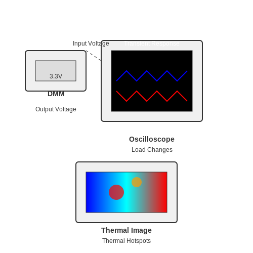
7. Latest Advancements in Circuit Design
7.1 Latest Advancements in Circuit Design
In recent years, the field of voltage regulation has seen significant innovation, driven by the need for more efficient, compact, and reliable power solutions. As the demands for power management in electronic devices increase, both engineers and researchers are utilizing a combination of advanced materials, novel topologies, and emerging technologies to enhance the performance of voltage regulators. One notable advancement involves the development of integrated circuit (IC) voltage regulators that feature adaptive control mechanisms. Traditional voltage regulation often encountered limitations when dealing with varying load conditions. In contrast, adaptive regulators dynamically adjust their control strategy based on real-time data, which results in improved response times and better voltage stability across a range of loads. This is particularly relevant in battery-powered applications, where efficiency directly affects runtime and operational performance. Another important trend is the integration of wide bandgap semiconductors, such as Gallium Nitride (GaN) and Silicon Carbide (SiC). These materials exhibit superior thermal conductivity and breakdown voltages compared to traditional silicon-based devices. Consequently, voltage regulators that utilize GaN or SiC components can operate at higher efficiencies and at higher temperatures. The adoption of these materials allows for more compact designs, enabling smaller and lighter power electronics that are crucial for modern applications such as electric vehicles and renewable energy systems. Advancements in digital control techniques have also transformed circuit design for voltage regulators. By employing microcontrollers or digital signal processors (DSPs), engineers can implement complex algorithms that optimize regulation performance. These algorithms can actively adjust for variations in input voltage and loading conditions, improve power factor, and enhance noise immunity. The ability of digital controllers to communicate and receive updates over networks allows for more sophisticated diagnostics and programmability, further adding versatility to voltage regulation systems. In the realm of power factors, emerging multi-level converter topologies are a noteworthy development. Multi-level converters improve the quality of the output voltage by reducing harmonic distortion, which is crucial for sensitive electronic equipment. These systems, along with advanced filtering techniques, contribute positively to overall power quality and system efficiency, making them integral to applications in industrial automation and renewable energy. Additionally, current trends in circuit design increasingly focus on miniaturization and integration. By leveraging microelectromechanical systems (MEMS) technology, various components of voltage regulators can be integrated on a single chip. This reduces the overall footprint and the number of interconnections, which minimizes potential points of failure, improves reliability, and simplifies the manufacturing process. Such developments are essential for portable and compact devices where space is at a premium. The practical implications of these advancements are vast. As industries push for higher performance from electronic components, the integration of new technologies in voltage regulation circuits not only enhances device reliability but also fosters innovation across various applications. Fields such as telecommunications, aerospace, and consumer electronics will benefit significantly from these developments, ensuring that power management systems meet the rigorous demands of contemporary devices. In summary, the latest advancements in circuit design for voltage regulators embrace a holistic approach, combining materials science, digital technology, and innovative topologies to meet the evolving needs of electronic power management. These developments position engineers and researchers alike to tackle future challenges in voltage regulation efficiently and effectively.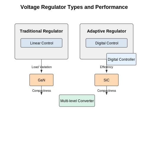
7.2 Future Trends in Voltage Regulation Technology
In the realm of voltage regulation, we are witnessing a transformative phase marked by rapid advancements in technology driven by several prominent trends. As the demand for efficient and stable power supply systems continues to mount, innovative approaches are being developed to address the complexities of modern electronics, ranging from consumer electronics to industrial applications. One of the most significant trends is the integration of digital control techniques in voltage regulation. Traditional linear and switching regulators often rely on analog feedback systems, but with the increasing capabilities of microcontrollers, digital solutions are becoming more popular. Digital voltage regulators offer enhanced performance due to their ability to adjust parameters dynamically and recover from transient conditions more effectively. This adaptability enables them to handle variations in load and input voltage, a feature particularly advantageous in renewable energy systems, where power supply can fluctuate significantly. Another exciting development is the growing use of Gallium Nitride (GaN) and Silicon Carbide (SiC) in power electronics. These wide-bandgap semiconductors afford higher efficiency and thermal performance compared to traditional silicon devices. This results in smaller, lighter voltage regulators that can operate at higher frequencies, allowing for miniaturization in applications like electric vehicles and aerospace systems, where space and weight are critical considerations. The robust physical properties of GaN and SiC enhance their reliability in extreme conditions, making them well-suited for high-voltage applications. The paradigm of multi-phase voltage regulation is also gaining traction. By employing multiple phases in voltage regulation, designers can distribute the current load across several pathways, effectively reducing the required size of each component and dissipating heat more evenly. Multi-phase systems can better accommodate transient loads, leading to enhanced overall stability and efficiency. This approach is vital in high-performance computing and data centers, where power integrity is paramount. Furthermore, advancements in energy harvesting technologies present new opportunities for voltage regulation. Devices that capture energy from ambient sources—such as light, heat, or motion—can benefit from specialized voltage regulators designed to manage very low power levels. These regulators not only extend battery life in portable gadgets but also contribute to the development of self-powered sensors and Internet of Things (IoT) applications. As battery technology evolves, especially with the advent of solid-state and advanced lithium-ion technologies, voltage regulators must also adapt. The need to efficiently manage the charging and discharging cycles while maintaining safety and longevity of batteries requires sophisticated regulation methods. Implementations such as *Battery Management Systems (BMS)* that utilize intelligent algorithms are key to optimizing battery performance. Lastly, the ongoing trend towards more environmentally friendly electronics has led to the development of voltage regulators that prioritize sustainability. The focus on reducing power consumption and minimizing waste aligns with global initiatives to reduce carbon footprints. Designing voltage regulators that incorporate eco-friendly materials and manufacturing processes is becoming a requisite in the industry. In summary, one can observe that the future of voltage regulation technology is characterized by the blending of traditional principles with groundbreaking innovations. The fusion of digital efficiency, advanced materials, enhanced designs, energy harvesting, and eco-conscious manufacturing creates a vibrant landscape that engineers and researchers can explore. Keeping abreast of these trends not only shapes the trajectory of voltage regulation technology but also lays the groundwork for sustainable and efficient power systems for future generations.8. Key Textbooks
8.1 Key Textbooks on Applied Voltage Regulators
- Design of Voltage Regulators for Next-Generation System-on-a-Chip Devices — This book offers a comprehensive approach to designing voltage regulators suitable for modern integrated circuits. It emphasizes the importance of low-power design and efficiency.
- Power Management Integrated Circuits — Offers insights into the integration of voltage regulators in power management systems, covering design, implementation, and efficiency enhancement in electronic circuits.
- Advanced Electronic Circuits and Devices — This book explores complex topics in electronic circuit design, including comprehensive discussions on the application and functionality of voltage regulators.
- Voltage Regulators: Design and Applications — A highly practical guide that outlines real-world scenarios and challenges in the design and implementation of voltage regulators, with numerous application examples.
- Electronics and Circuit Analysis Using MATLAB — This book provides readers with computational tools useful in analyzing electronic circuits, including voltage regulators, using MATLAB simulations.
- Modern Power Electronics and AC Drives — Offers an extensive overview of how voltage regulators play critical roles in power electronics and their applications in AC drive systems.
- Power Electronics: Devices, Drivers, Applications, and Passive Components — This textbook covers fundamental concepts in power electronics and delves into detailed applications of voltage regulators within various circuit configurations.
8.2 Research Papers
- A Review of Voltage Regulators for Future Distribution Networks — This paper discusses the evolution and future prospects of voltage regulation mechanisms in distribution networks, pinpointing technological advancements that enhance efficiency and reliability.
- Novel Control Strategies for Smart Voltage Regulators — The study highlights innovative control strategies for voltage regulators in smart grid applications, focusing on dynamic response and improved performance metrics.
- Advancements in Voltage Regulators for Renewable Energy Systems — An exploration into the role of voltage regulators in renewable energy systems, emphasizing integration challenges and solutions for solar and wind power applications.
- Voltage Regulation Challenges in Microgrids — Provides an in-depth analysis of voltage regulation strategies within microgrids, detailing technological hurdles and prospective innovations that address emerging needs.
- Analysis of Voltage Regulation Technologies for Low-Voltage Networks — This research examines traditional and cutting-edge voltage regulation technologies deployed in low-voltage networks, offering comprehensive performance evaluations.
- Smart Voltage Regulators: Concepts and Applications — Covers the principles and large-scale applications of smart voltage regulators, linking theoretical concepts to real-world implementations in evolving power systems.
- Voltage Regulation Approaches in Distribution Systems — This paper discusses various approaches to voltage regulation within distribution systems, providing a comparative analysis of passive and active methods.
8.3 Online Resources
- Voltage Regulators Tutorial — Provides a comprehensive overview of various voltage regulators, illustrating their principles of operation, types, and real-world applications. It's ideal for gaining a deeper understanding of how these components maintain consistent voltage levels in electronics.
- Microchip Technology Linear Voltage Regulators — Offers detailed specifications and datasheets for an extensive range of linear voltage regulators. This resource is valuable for selecting the appropriate regulator based on performance parameters required in specific electronics projects.
- Texas Instruments Linear Regulators — Features an array of linear regulators with applications notes, evaluation modules, and design resources. These tools assist engineers in comprehensively analyzing regulator performance and implementation strategies.
- Analog Devices Linear Regulators — Provides access to an assortment of linear regulators with supporting technical articles, application guides, and design simulations, valuable for researchers and engineers working on low-noise applications.
- Digi-Key Electronics: Basics of Electronic Voltage Regulation — Offers a detailed educational guide on voltage regulation fundamentals, including types and practical considerations. This tutorial equips readers with the foundational knowledge to apply voltage regulators in diverse electronic systems.
- Linear Voltage Regulators: Basics and Working Principle — This page explains the operating principles and characteristics of linear voltage regulators, providing helpful diagrams and typical applications which serve as a reference for design engineers.
- EEWeb Voltage Regulators Study Guide — An extensive study guide that delves into the different configurations and types of voltage regulators, their functionalities, and selection criteria. This resource aids in understanding applications in specific electronic circuits.
- EE Times Articles on Voltage Regulators — Contains a collection of scholarly articles and industry news focusing on advances and trends in voltage regulator technology. It's beneficial for staying informed about the latest research and product innovations.