


Unity gain Inverter amplifier circuit
#op-amp
#unity gain
#inverter amplifier
#LT1012
#LT1022
#low drift
#high speed
#summing node
#resistors

Description: The circuit comprises a low drift LT1012 device and a high-speed amplifier LT1022. It functions as a unity gain inverter, with the summing node located at the junction of three 10k ohm resistors. The circuit monitors the summing node of the LT1012, compares it to a reference, and drives the positive input of the LT1022, thereby completing a feedback loop to stabilize around the LT1022 output. The time constant of the LT1012, limited by a capacitor ranging from 10 to 300 pF, restricts its response to low-frequency signals. The LT1022 is responsible for handling high-frequency inputs while the LT1012 stabilizes the operating point.
Additionally, the resistances in the range of 4.7 to 220 ohms at the LT1022 serve as a voltage divider to prevent excessive input overdrive during startup. This circuit integrates the LT1012, which has a noise level of 35 pV and an offset drift of 1.5 to 23 µV/°C, with the LT1022, which features a slew rate of 300 V/µs and a bandwidth of 300 kHz for full power operation. The bias current, primarily influenced by the LT1012, is approximately 100 pA.
The described circuit is a precision analog signal processing system that leverages the characteristics of both the LT1012 and LT1022 components. The LT1012, known for its low offset voltage and low drift, is ideal for applications requiring high accuracy and stability in low-frequency environments. The integration of a capacitor at the LT1012's output allows for the filtering of high-frequency noise, ensuring that only the desired low-frequency signals are processed.
In contrast, the LT1022 amplifier is optimized for high-speed applications, capable of handling rapid changes in input signals with minimal distortion. The feedback mechanism established through the summing node allows for real-time adjustments, ensuring that the output remains stable even with variations in input conditions. The use of a resistor divider at the LT1022 input is a critical design choice, as it mitigates the risk of overdriving the amplifier during power-up, thus protecting the circuit from potential damage.
Overall, this circuit design exemplifies the careful consideration of component characteristics and operational parameters, resulting in a robust solution for applications requiring both low-frequency stability and high-frequency responsiveness.The circuit consists of a device with low drift LTl012. and a speed amplifier LTl022Jligh. The entire circuit is a unity gain inverter, with the summing node at the junction of three resistors 10k. The monitors what the Tl012 summing node, it compares to the mass, and drives the positive input LTI022, completing a loop to stabilize around the Tl022 L.
The k 10 to 300 pF at the time constant LTI012 limit its response to low frequency signals. LTl022 handles the high-frequency inputs while LTl012 stabilizes the operating point. The k from 4.7 to 220 ohms at Tl022 The divider prevents excessive input overdrive at startup. This circuit combines LTl012 of 35 pV and offset drift of 1.5 to 23 REFER LTl022 V / ps slew rate and 300 kHz bandwidth for full power. bias current, dominated by the LTl012, is about 100 pA.
Additionally, the resistances in the range of 4.7 to 220 ohms at the LT1022 serve as a voltage divider to prevent excessive input overdrive during startup. This circuit integrates the LT1012, which has a noise level of 35 pV and an offset drift of 1.5 to 23 µV/°C, with the LT1022, which features a slew rate of 300 V/µs and a bandwidth of 300 kHz for full power operation. The bias current, primarily influenced by the LT1012, is approximately 100 pA.
The described circuit is a precision analog signal processing system that leverages the characteristics of both the LT1012 and LT1022 components. The LT1012, known for its low offset voltage and low drift, is ideal for applications requiring high accuracy and stability in low-frequency environments. The integration of a capacitor at the LT1012's output allows for the filtering of high-frequency noise, ensuring that only the desired low-frequency signals are processed.
In contrast, the LT1022 amplifier is optimized for high-speed applications, capable of handling rapid changes in input signals with minimal distortion. The feedback mechanism established through the summing node allows for real-time adjustments, ensuring that the output remains stable even with variations in input conditions. The use of a resistor divider at the LT1022 input is a critical design choice, as it mitigates the risk of overdriving the amplifier during power-up, thus protecting the circuit from potential damage.
Overall, this circuit design exemplifies the careful consideration of component characteristics and operational parameters, resulting in a robust solution for applications requiring both low-frequency stability and high-frequency responsiveness.The circuit consists of a device with low drift LTl012. and a speed amplifier LTl022Jligh. The entire circuit is a unity gain inverter, with the summing node at the junction of three resistors 10k. The monitors what the Tl012 summing node, it compares to the mass, and drives the positive input LTI022, completing a loop to stabilize around the Tl022 L.
The k 10 to 300 pF at the time constant LTI012 limit its response to low frequency signals. LTl022 handles the high-frequency inputs while LTl012 stabilizes the operating point. The k from 4.7 to 220 ohms at Tl022 The divider prevents excessive input overdrive at startup. This circuit combines LTl012 of 35 pV and offset drift of 1.5 to 23 REFER LTl022 V / ps slew rate and 300 kHz bandwidth for full power. bias current, dominated by the LTl012, is about 100 pA.

3 Band Graphic Equalizer
This simple equalizer utilizes a single operational amplifier (op-amp) and provides three frequency ranges: low frequency, mid frequency, and high frequency. With the specified component values, it achieves approximately ±20 dB of gain or attenuation at frequencies of 50 Hz,...

op amp 6 line audio mixer circuit
The microphone inputs are amplified approximately 100 times or 40 dB, with the total gain of the mixer, including the summing amplifier, reaching 46 dB. The microphone input is designed for microphones that produce an output of around 2 mV...
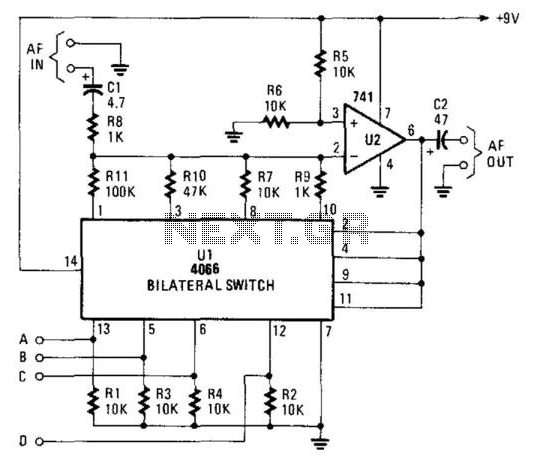
Gain-Controlled Op Amp
The gain controller utilizes a 4066 quad bilateral switch to electronically select a feedback resistor for the 741 operational amplifier. One or more switches can be activated simultaneously to achieve a stepped, variable-gain range from less than 1 to 100.
The...

Low-Cost Logarithmic Converter Using Opamp and Transistor
This low-cost logarithmic converter is constructed using an operational amplifier (op-amp) and a transistor. The circuit utilizes a Motorola MC1539G op-amp connected to a PNP transistor.
The logarithmic converter circuit is designed to convert linear input signals into logarithmic output signals,...

op amp Twin T circuit noisy
The circuit is constructed on a breadboard and produces the expected sound characteristics, specifically a damped sine wave reminiscent of large 808/909-style kicks. However, it exhibits a significant amount of noise. An attempt was made to mitigate this by adding...

Light sensitive switch
A light-sensitive switch, also known as a dark-sensitive switch, is a specialized switch that utilizes an operational amplifier integrated circuit (IC) LM74 in conjunction with a light-dependent resistor (LDR).
The light-sensitive switch circuit operates by detecting ambient light levels and...

Dynamo Frequency Monitor
IC1 is a dual operational amplifier. In this circuit, each op-amp functions as a voltage comparator. When the voltage at the positive input exceeds the voltage at the negative input, the output transitions to a high state. Conversely, when the...

Noninverted Unity-Gain Amplifier Circuit
An operational amplifier (op amp) can function as a unity gain amplifier by connecting its output to its inverting input as illustrated. The load resistance (Rl) should be sufficiently low to prevent the op amp's bias current from introducing a...

Doppler Rdf
The power supply consists of a 7812 voltage regulator followed by an operational amplifier (op-amp) configured to output 6V, which serves as a midpoint supply voltage for the audio op-amp stages. A 12V regulator is deemed excessive for battery-powered applications....