


Circuit diagram for basic alarm with delayed trigger
#CD4001
#NOR gate
#alarm system
#delayed trigger
#security circuit
#5-15Vdc
#quad 2-input
#simple alarm
#voltage transition
#versatile IC
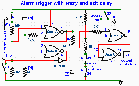
Description: The CD4001 quad 2-input NOR gate is a highly versatile integrated circuit (IC) that can be utilized in numerous applications. This example demonstrates its use in a simple alarm system. The recommended power supply voltage for the CD4001 ranges from 5 to 15V DC. The typical transition voltage is approximately 50% of the supply voltage, with a variation range of 30% to 70%. The delay in the circuit is determined by the resistor-capacitor (R1/C1) combination; for instance, using R1=680kΩ and C1=10µF results in an approximate delay of 8 seconds. This delay allows time to set the module to "Standby" and exit within the specified period before the alarm is triggered. Upon re-entering, the alarm must be reset within this delay period. Gate A functions as the trigger circuit, while gates B and C generate an 800Hz tone for the speaker, activated by a transistor. In an additional circuit, an extra gate has been included to provide an automatic/delayed turn-off function. Capacitor C2 and resistor R2 are employed to automatically deactivate the alarm. Similar to C1 and R1, C2 and R2 can be selected to define the duration for which the alarm remains active before being turned off. The system must be reset for reactivation. Two outputs are available as illustrated. However, the delay period may not be sufficient for a manual reset. To address this, an integrated auto-exit/entry delay is proposed, eliminating the need for manual reset as depicted in the subsequent circuit. The R1/C1 and R2/C2 configurations establish the exit/entry delay circuits. When power is initially supplied (in standby mode), all sensor switches (S3, S4) are enabled, except for S1a/b, which is disabled for a predetermined duration through the time-delay network C1/R1. At the conclusion of this interval, S1 is automatically enabled. When S1 is activated, the output of gate A transitions to a high state and is latched by the action of diode D1 (1N4148) and gate D. This high output voltage is then directed to the input of gate B via the C2/R2 delay network, and after a predetermined delay, the voltage at gate B rises sufficiently to trigger the alarm.
The CD4001 quad 2-input NOR gate is a fundamental building block in digital electronics, offering flexibility in design and application. In this alarm system, the gates are configured to create a logic circuit that can manage both the triggering and deactivation of the alarm. The integration of R1 and C1 provides a time delay that is critical for user interaction, allowing the user to enter a code or perform necessary actions without immediate triggering of the alarm. The choice of resistor and capacitor values directly influences the performance of the delay mechanism, enabling customization based on specific user requirements or system constraints.
The addition of the automatic turn-off feature is particularly beneficial in scenarios where manual intervention may be impractical. By utilizing C2 and R2, the system ensures that the alarm will not remain active indefinitely, thus conserving power and preventing unnecessary disturbances. The careful selection of component values for these delay circuits allows for a wide range of operational durations, making the system adaptable to various environments and security needs.
The use of diodes in the circuit, such as the 1N4148, plays a crucial role in maintaining the integrity of the logic levels and ensuring that the alarm system operates reliably. The diode's ability to prevent backflow of current protects sensitive components and stabilizes the circuit during operation. Overall, the design exemplifies the effective use of the CD4001 NOR gate in creating a practical and efficient alarm system, showcasing the versatility and functionality of this integrated circuit in real-world applications.The CD4001 quad 2-input NOR gate is a very versatile IC that can be used in an almost infinite variation. Here we will use it in the application of a simple alarm system. The power supply suggested for the CD4001 is 5 to 15Vdc Max. The CD4001 has a typical transition voltage value of 50% of its supply voltage with a possible spread of 30% to 70% d
epending on its production. The delay is set by R1/C1) for exemple, R1=680k and C1=10uf give a time delay of approx 8 secs. Thus time can adjusted by the choice of R/C values. This delayed trigger allows time to set the module in the "Standby" and exit within the time delay period before the alarm is triggered. Again on re-entering the alarm must be reset within that delay period. Gate A forms the trigger circuit and gates B&C form a tone generator of 800hz to the speaker activated by the transistor.
In the next circuit in addition to the delay ON circuit we added an extra gate to provide for an auto/delayed turn off function. C2 & R2 are used to automatically turn off the alarm. Like C1 & R1, C2 & R2 can be selected for the duration the alarm will stay on then automatically turned off.
It must be reset to be reactivated. Two outputs are available as shown. But, the delay period may not be long enought to manually reset the unit. We can eliminate the guess work by integrating an auto-exit /entry delay that will not require a manual reset as shown in the next circuit. R1/C1 and R2/C2 forms the exit /entry delay ciruits. When the power is first applied (standby) all sensor switches (S3, S4) are enabled except S1a/b which is disabled for a pre-set period via time-delay network C1/R1.
At the end of this period S1 is automatically enabled. When S1 is activated the output of gate-A goes high and is locked by the action of D1 diode(1N4148) and gate-D. This high output voltage is applied to the input of gate-B via C2/R2 delay network an after a pre-set delay the voltage reaching gate-B rises to such a value that the alarm is activated.
The CD4001 quad 2-input NOR gate is a fundamental building block in digital electronics, offering flexibility in design and application. In this alarm system, the gates are configured to create a logic circuit that can manage both the triggering and deactivation of the alarm. The integration of R1 and C1 provides a time delay that is critical for user interaction, allowing the user to enter a code or perform necessary actions without immediate triggering of the alarm. The choice of resistor and capacitor values directly influences the performance of the delay mechanism, enabling customization based on specific user requirements or system constraints.
The addition of the automatic turn-off feature is particularly beneficial in scenarios where manual intervention may be impractical. By utilizing C2 and R2, the system ensures that the alarm will not remain active indefinitely, thus conserving power and preventing unnecessary disturbances. The careful selection of component values for these delay circuits allows for a wide range of operational durations, making the system adaptable to various environments and security needs.
The use of diodes in the circuit, such as the 1N4148, plays a crucial role in maintaining the integrity of the logic levels and ensuring that the alarm system operates reliably. The diode's ability to prevent backflow of current protects sensitive components and stabilizes the circuit during operation. Overall, the design exemplifies the effective use of the CD4001 NOR gate in creating a practical and efficient alarm system, showcasing the versatility and functionality of this integrated circuit in real-world applications.The CD4001 quad 2-input NOR gate is a very versatile IC that can be used in an almost infinite variation. Here we will use it in the application of a simple alarm system. The power supply suggested for the CD4001 is 5 to 15Vdc Max. The CD4001 has a typical transition voltage value of 50% of its supply voltage with a possible spread of 30% to 70% d
epending on its production. The delay is set by R1/C1) for exemple, R1=680k and C1=10uf give a time delay of approx 8 secs. Thus time can adjusted by the choice of R/C values. This delayed trigger allows time to set the module in the "Standby" and exit within the time delay period before the alarm is triggered. Again on re-entering the alarm must be reset within that delay period. Gate A forms the trigger circuit and gates B&C form a tone generator of 800hz to the speaker activated by the transistor.
In the next circuit in addition to the delay ON circuit we added an extra gate to provide for an auto/delayed turn off function. C2 & R2 are used to automatically turn off the alarm. Like C1 & R1, C2 & R2 can be selected for the duration the alarm will stay on then automatically turned off.
It must be reset to be reactivated. Two outputs are available as shown. But, the delay period may not be long enought to manually reset the unit. We can eliminate the guess work by integrating an auto-exit /entry delay that will not require a manual reset as shown in the next circuit. R1/C1 and R2/C2 forms the exit /entry delay ciruits. When the power is first applied (standby) all sensor switches (S3, S4) are enabled except S1a/b which is disabled for a pre-set period via time-delay network C1/R1.
At the end of this period S1 is automatically enabled. When S1 is activated the output of gate-A goes high and is locked by the action of D1 diode(1N4148) and gate-D. This high output voltage is applied to the input of gate-B via C2/R2 delay network an after a pre-set delay the voltage reaching gate-B rises to such a value that the alarm is activated.

Circuit Diagram 6 zone alarm independent
This circuit is a 6-zone alarm system designed for independent operation, suitable for small office or home environments. It can be adapted to utilize a combination lock or keypad for setting and resetting the alarm. All zones, Z1 to Z6,...

5 Zone Alarm System
This is a complete alarm system with five independent zones suitable for a small office or home environment. It utilizes three CMOS integrated circuits and features a timed entry/exit zone, four immediate zones, and a panic button. There are indicators...

6 Zone Alarm System
This alarm system features six independent zones, one timed entry/exit zone, a seven-segment LED display, and a test or walkthrough capability. It is designed for use in small office or home environments and can be adapted to utilize a combination...

Audio CD4001 based on Car Alarm Circuit
This is a simple alarm circuit using a CD4001 integrated circuit. It is designed for home, motorcycle, car, or other applications. The circuit will undergo computer simulation using Livewire, followed by printed circuit design with KiCad. SW1 is a normally...

Optical Direction Discriminator Circuit
The circuit utilizes two CD4001 packages, incorporating eight NOR gates. It operates by receiving pulse streams that are input to an RS flip-flop, producing an output waveform with a variable duty cycle based on the direction of rotation. The input...

Doorbell Sound with CD4001 CD4060
The doorbell sound circuit produces a two-tone sound. The circuit operates with switch S1. The integrated circuit IC1 functions as a frequency division circuit and generates sound frequencies through components C1 and R1. The audio signal is transmitted from pin...

Two-Zone Alarm
This is a two-zone alarm system featuring automatic exit, entry, and siren cut-off timers. It can be activated by standard normally-closed input devices such as magnetic reed contacts, foil tape, and passive infrared sensors (PIRs). The circuit is designed to...

Auto-advance projector
The circuit is constructed using a 4001 quad two-input NOR gate, allowing for switch-selectable auto-advance times of 5, 10, 15, 20, 25, or 30 seconds through the remote control socket of a projector. Ula and Ulb create an astable multivibrator,...

5 zone alarm circuit
This is a complete alarm system with five independent zones suitable for a small office or home environment. It utilizes three CM integrated circuits and features a timed entry/exit zone, four immediate zones, and a panic button. There are indicators...