


Optical Direction Discriminator Circuit
#CD4001
#NOR gates
#RS flip flop
#duty cycle
#direction detection
#pulse trains
#rotation sensor
#digital circuit

Description: The circuit utilizes two CD4001 packages, incorporating eight NOR gates. It operates by receiving pulse streams that are input to an RS flip-flop, producing an output waveform with a variable duty cycle based on the direction of rotation. The input pulses are also directed to a NOR gate, which combines the two pulse trains. The rising edges of this combined waveform generate brief positive pulses through a circuit composed of R1, C1, D3, and a NOR gate configured as an inverter. This setup samples the outputs of the flip-flop to ascertain the direction of rotation. Furthermore, when the output has a large duty cycle, it compels the sampling NOR gate to create a pulse train that continuously sets or resets the second RS flip-flop, thereby providing a constant indication of the rotation direction.
The described circuit leverages the CD4001 NOR gate IC to create a simple yet effective rotational direction detector. The RS flip-flop serves as a memory element that retains the state corresponding to the direction of rotation, which is determined by the input pulse frequency and duty cycle. The integration of R1, C1, and D3 in conjunction with the NOR gate inverter is crucial for generating short pulses that are essential for accurate sampling of the flip-flop outputs.
In this arrangement, the first RS flip-flop captures the state of the incoming pulse stream, while the second RS flip-flop is used to provide a stable output indicating the direction of rotation. When the input pulses exhibit a high duty cycle, the resultant output from the first flip-flop leads to a consistent pulse train from the sampling NOR gate. This pulse train is instrumental in toggling the second RS flip-flop, ensuring that the output remains in a state that reflects the current rotational direction.
The circuit's design is particularly advantageous for applications requiring real-time monitoring of rotational motion, such as in motor control systems or rotary encoders. The use of standard logic components like the CD4001 allows for straightforward implementation and integration into larger systems. The simplicity of the design, combined with the reliability of the NOR gate logic, makes this circuit an ideal choice for detecting and indicating the direction of rotation in various electronic applications. The very simple circuit uses only two CD4001 packages, i.e., eight NOR gates and operates in the following way: Pulse streams are fed to an RS flip flop generating an output waveform wliich has a small or large duty cycle depending on the direction of rotation, The same input pulses are also fed to a NOR gate, which adds the two pulse trains. The rising edges of this waveform are used to produce short positive pulses from the circuit consisting of Rl, CI, D3, and a NOR gate used as an inverter.
This is used to sample the outputs of the flip flop to detect the direction of rotation. The output, whose duty cycle is large, forces the sampling NOR gate to generate a pulse train which sets (or resets) the second RS flip-flop continuously giving a permanent indication of the direction of rotation.
The described circuit leverages the CD4001 NOR gate IC to create a simple yet effective rotational direction detector. The RS flip-flop serves as a memory element that retains the state corresponding to the direction of rotation, which is determined by the input pulse frequency and duty cycle. The integration of R1, C1, and D3 in conjunction with the NOR gate inverter is crucial for generating short pulses that are essential for accurate sampling of the flip-flop outputs.
In this arrangement, the first RS flip-flop captures the state of the incoming pulse stream, while the second RS flip-flop is used to provide a stable output indicating the direction of rotation. When the input pulses exhibit a high duty cycle, the resultant output from the first flip-flop leads to a consistent pulse train from the sampling NOR gate. This pulse train is instrumental in toggling the second RS flip-flop, ensuring that the output remains in a state that reflects the current rotational direction.
The circuit's design is particularly advantageous for applications requiring real-time monitoring of rotational motion, such as in motor control systems or rotary encoders. The use of standard logic components like the CD4001 allows for straightforward implementation and integration into larger systems. The simplicity of the design, combined with the reliability of the NOR gate logic, makes this circuit an ideal choice for detecting and indicating the direction of rotation in various electronic applications. The very simple circuit uses only two CD4001 packages, i.e., eight NOR gates and operates in the following way: Pulse streams are fed to an RS flip flop generating an output waveform wliich has a small or large duty cycle depending on the direction of rotation, The same input pulses are also fed to a NOR gate, which adds the two pulse trains. The rising edges of this waveform are used to produce short positive pulses from the circuit consisting of Rl, CI, D3, and a NOR gate used as an inverter.
This is used to sample the outputs of the flip flop to detect the direction of rotation. The output, whose duty cycle is large, forces the sampling NOR gate to generate a pulse train which sets (or resets) the second RS flip-flop continuously giving a permanent indication of the direction of rotation.

Audio CD4001 based on Car Alarm Circuit
This is a simple alarm circuit using a CD4001 integrated circuit. It is designed for home, motorcycle, car, or other applications. The circuit will undergo computer simulation using Livewire, followed by printed circuit design with KiCad. SW1 is a normally...

Duty-cycle-monitor
The circuit monitors and displays a digital signal's duty cycle with an accuracy of ±1%. By using switch S2, users can select a frequency range of either 250 Hz to 2.5 kHz with ±1% accuracy or 2 kHz to 50...

direction detector decoder
This circuit was designed to monitor the traffic of bumblebees entering and exiting the hive, distinguishing between a-to-b motion and b-to-b motion. When paired with an optical decoder, the circuit can differentiate between clockwise and counterclockwise rotation, delivering a resolution...

Direction-detector-decoder
This circuit was designed to monitor the traffic of bumblebees entering and exiting the hive, distinguishing between a-to-b motion and b-to-b motion. When paired with an optical decoder, the circuit differentiates between clockwise and counterclockwise rotation, providing a resolution of...

Duty Cycle Selector
The Duty Cycle Selector is a unique project designed to select the duty cycle in 9 steps up to 100%. It includes a circuit diagram and a description of the duty cycle selector and various digital circuits.
The Duty Cycle Selector...

CD4001 composed of single-channel modulator
The core elements of this circuit are the second four-input NOR gate terminal IC CD4001. The entire circuit features a simple structure, with fewer components, making it easy to construct, particularly for remote control transmitters or carrier modulation transmission. The...
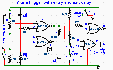
Circuit diagram for basic alarm with delayed trigger
The CD4001 quad 2-input NOR gate is a highly versatile integrated circuit (IC) that can be utilized in numerous applications. This example demonstrates its use in a simple alarm system. The recommended power supply voltage for the CD4001 ranges from...

Doorbell Sound with CD4001 CD4060
The doorbell sound circuit produces a two-tone sound. The circuit operates with switch S1. The integrated circuit IC1 functions as a frequency division circuit and generates sound frequencies through components C1 and R1. The audio signal is transmitted from pin...

Duty-Cycle Measurer
An Intersil 7101 31/2-digit A/D converter is utilized to display the duty cycle of a pulse train as a percentage. The frequency range of this circuit is from 100 Hz to 250 kHz. CMOS gates are employed to convert the...