


doorbell circuit diagram

Description: The simple bell circuit without IC. It includes a doorbell circuit that can produce different sounds using integrated circuits, transistors, and resistors. The circuit utilizes a coded trigger mechanism to differentiate between various visitors. When the button is pressed, it activates an output that generates audio signals, which are amplified and sent to a speaker to produce distinct sounds. The circuit can be customized to create different tones for different buttons.
The described circuit operates as a basic electronic doorbell capable of producing multiple tones to identify different visitors. It employs a combination of integrated circuits (ICs), transistors, and resistors to achieve this functionality. The design features a coded trigger circuit activated by pressing a button, which sends a signal through an AND gate formed by the inputs of an integrated circuit (ICI).
When a button is pressed, such as S6, it generates a high signal at the base of transistor V1, which in turn triggers the polyphonic sound generator circuit (IC2). This circuit is responsible for producing various audio outputs, which are amplified by transistor V4 and delivered through a speaker (BL). The output is designed to emit a distinct sound, such as a "bang" or ringing tone, depending on the button pressed.
The circuit can also respond to multiple buttons: pressing S5 activates a different pathway through the circuit, allowing a unique sound to be generated. Similarly, pressing buttons S1 to S3 engages additional inputs of IC1, leading to yet another distinct audio output. This versatility allows users to assign different sounds to each button, enhancing the functionality of the doorbell system.
In summary, the simple bell circuit integrates a coded trigger mechanism, audio signal generation, and amplification to create a customizable doorbell system. It exemplifies the use of basic electronic components to achieve a practical and user-friendly application in home automation.The simple bell circuit without IC reward points: 0 | solution time : 10:20 | Asked by: Zhang Dan QiaoThanks for Related Content who simply doorbell doorbell circuit 19 music circuit, integrated circuits, transistors and resistors, respectively, what is the role of integrated FM wireless microphone circuit 5 42008-12 Who is the application of IC 7 4 123 -8 IC phase detector schematic diagram problems with the theme: integrated circuit doorbell forwarded to: Texas Instruments cd40106b sponsored links The of logic chips, logic devices and to provide professional solutions, triggers, Little Logic, reverse, etc. the world and of science and technology agency ad706jr, the price advantage You have to make their own doorbell, the doorbell will not be installed or bought The market are using the AC exchange doorbell doorbell, a battery with the use of electronic doorbell wiring, there is no electronic doorbell wiring.
I do not know what kind your doorbell Tomorrow I will come again. Help me answer time of | to the TA for helpRelated Content doorbell circuit 123 is what Urgent! ! ! (Physical) 13 19 who do not have a simple schematic of integrated circuits doorbell doorbell circuit 3 simple building intercom door step pick up the sun can hear the sound, can open the door, but the doorbell did not sound, how to make it sound, . 10 class with 90 to make a simple transistor amplifier circuit 5 more issues with the theme: doorbell circuit were two other answers Three days of scientific information on the book and the accompanying detailed description, if not enough to remove the door look at home respondents: aloof bound alone | Bell, should be a separate electronic components, this would not have a map of it, can affect the kind of power!
The simplest circuit that is two wires, a switch, a power supply, cable giant to not talk of it. sweat. respondents: csuhyycx | Add bell alarms chip production and marketing cost-effective Huarong Tai companies to provide customers with better service Shenzhen Security Group list well-known brands of CCTV video doorbell! This example describes the production of digital circuits using a three-tone electronic doorbell, it can be set on the button, then the output of the sound is different, so as to achieve the purpose of distinction as visitors.
Coded trigger circuit from the button Sl-S6, the second four input AND gate (DI, D2) integrated circuit ICI, resistors Rl-Rll and transistors Vl-V3 and so on. Polyphonic sound generator circuit by the analog integrated circuit train IC2, light-emitting diode VLl and VL2 and the composition resistors R13-Rl Audio from the audio amplifier and speaker amplifier tubes V4 BL composition.
When pressed during S6, Vl input due to high base and turn in the big end of IC2`s TRl generate low input trigger pulse, triggered by the work of the IC2, its O / P-side output audio signals The signal is amplified by the V4, sent the train through the speaker BL start of the "bang when" sound. When the same time when pressing the call, and S5, ICl U circuit within the 4 inputs Dl are high, its output can output high pulse, then V2 conduction, in the big end of IC2`s output to generate TR2 low trigger pulse, IC2 G‚ · triggered by the work, from the O / P-side output composite audio signal, the signal is amplified by the W, the drive train speaker BL issued a ringing start crossing the "bang when" sound.
When the same time when pressing the S1-S3, IC1 D2 within the gate were the big end of 4 input goes high, its output also goes high, the V3 turn, lost in the big end of IC2`s TR4 have low trigger pulse, IC2 is triggered by the work, from the O / P-side output composite audio signal, the signal amplified by the V4, driven speaker BL issued a "whistle running rings orbit as" a combination of sounds. Own large ring a bell, you can also press 51-53. Family and friends rang the doorbell, you can tell them "secret" and let them pres
The described circuit operates as a basic electronic doorbell capable of producing multiple tones to identify different visitors. It employs a combination of integrated circuits (ICs), transistors, and resistors to achieve this functionality. The design features a coded trigger circuit activated by pressing a button, which sends a signal through an AND gate formed by the inputs of an integrated circuit (ICI).
When a button is pressed, such as S6, it generates a high signal at the base of transistor V1, which in turn triggers the polyphonic sound generator circuit (IC2). This circuit is responsible for producing various audio outputs, which are amplified by transistor V4 and delivered through a speaker (BL). The output is designed to emit a distinct sound, such as a "bang" or ringing tone, depending on the button pressed.
The circuit can also respond to multiple buttons: pressing S5 activates a different pathway through the circuit, allowing a unique sound to be generated. Similarly, pressing buttons S1 to S3 engages additional inputs of IC1, leading to yet another distinct audio output. This versatility allows users to assign different sounds to each button, enhancing the functionality of the doorbell system.
In summary, the simple bell circuit integrates a coded trigger mechanism, audio signal generation, and amplification to create a customizable doorbell system. It exemplifies the use of basic electronic components to achieve a practical and user-friendly application in home automation.The simple bell circuit without IC reward points: 0 | solution time : 10:20 | Asked by: Zhang Dan QiaoThanks for Related Content who simply doorbell doorbell circuit 19 music circuit, integrated circuits, transistors and resistors, respectively, what is the role of integrated FM wireless microphone circuit 5 42008-12 Who is the application of IC 7 4 123 -8 IC phase detector schematic diagram problems with the theme: integrated circuit doorbell forwarded to: Texas Instruments cd40106b sponsored links The of logic chips, logic devices and to provide professional solutions, triggers, Little Logic, reverse, etc. the world and of science and technology agency ad706jr, the price advantage You have to make their own doorbell, the doorbell will not be installed or bought The market are using the AC exchange doorbell doorbell, a battery with the use of electronic doorbell wiring, there is no electronic doorbell wiring.
I do not know what kind your doorbell Tomorrow I will come again. Help me answer time of | to the TA for helpRelated Content doorbell circuit 123 is what Urgent! ! ! (Physical) 13 19 who do not have a simple schematic of integrated circuits doorbell doorbell circuit 3 simple building intercom door step pick up the sun can hear the sound, can open the door, but the doorbell did not sound, how to make it sound, . 10 class with 90 to make a simple transistor amplifier circuit 5 more issues with the theme: doorbell circuit were two other answers Three days of scientific information on the book and the accompanying detailed description, if not enough to remove the door look at home respondents: aloof bound alone | Bell, should be a separate electronic components, this would not have a map of it, can affect the kind of power!
The simplest circuit that is two wires, a switch, a power supply, cable giant to not talk of it. sweat. respondents: csuhyycx | Add bell alarms chip production and marketing cost-effective Huarong Tai companies to provide customers with better service Shenzhen Security Group list well-known brands of CCTV video doorbell! This example describes the production of digital circuits using a three-tone electronic doorbell, it can be set on the button, then the output of the sound is different, so as to achieve the purpose of distinction as visitors.
Coded trigger circuit from the button Sl-S6, the second four input AND gate (DI, D2) integrated circuit ICI, resistors Rl-Rll and transistors Vl-V3 and so on. Polyphonic sound generator circuit by the analog integrated circuit train IC2, light-emitting diode VLl and VL2 and the composition resistors R13-Rl Audio from the audio amplifier and speaker amplifier tubes V4 BL composition.
When pressed during S6, Vl input due to high base and turn in the big end of IC2`s TRl generate low input trigger pulse, triggered by the work of the IC2, its O / P-side output audio signals The signal is amplified by the V4, sent the train through the speaker BL start of the "bang when" sound. When the same time when pressing the call, and S5, ICl U circuit within the 4 inputs Dl are high, its output can output high pulse, then V2 conduction, in the big end of IC2`s output to generate TR2 low trigger pulse, IC2 G‚ · triggered by the work, from the O / P-side output composite audio signal, the signal is amplified by the W, the drive train speaker BL issued a ringing start crossing the "bang when" sound.
When the same time when pressing the S1-S3, IC1 D2 within the gate were the big end of 4 input goes high, its output also goes high, the V3 turn, lost in the big end of IC2`s TR4 have low trigger pulse, IC2 is triggered by the work, from the O / P-side output composite audio signal, the signal amplified by the V4, driven speaker BL issued a "whistle running rings orbit as" a combination of sounds. Own large ring a bell, you can also press 51-53. Family and friends rang the doorbell, you can tell them "secret" and let them pres

Two-phase squarewave oscillator
This circuit is one of the simplest to implement but can be challenging to comprehend. It consists of a two-transistor oscillator known as an astable multivibrator, which generates a square wave output that is out of phase. Initially, it is...
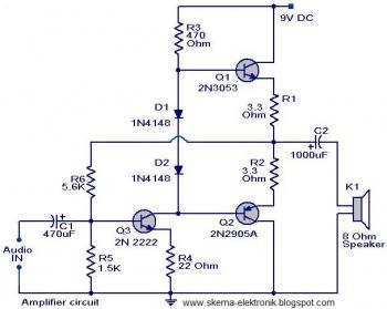
simple audio amplifier
The initial section of the circuit is a preamplifier that utilizes transistor Q1 (2N2222). The collector of transistor Q3 is connected to the base of transistor Q2 (2N2905A), which creates a complementary symmetry pair with Q3 (2N3053). The amplified signal...
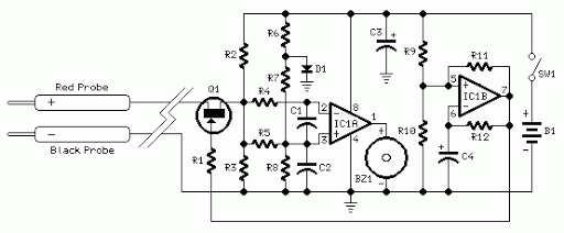
Quick On-Board Junction TesterCircuit
Acoustic check of transistor and diode junctions. Also suitable as a continuity tester. Short circuits or broken PCB tracks can be easily recognized.
The acoustic check of transistor and diode junctions is a method used to assess the functionality of these...

A common collector amplifier
A common collector amplifier circuit structure and its key components are outlined. The composition of the common collector amplifier circuit is fundamentally similar to that of a common emitter amplifier circuit, with two notable exceptions: one is the collector resistor...

Camera flash circuit
A simple transistor generator and transformer converts a 1.5V battery voltage to several hundred volts. This high voltage current then passes through a diode, which rectifies the current to DC. This DC current is stored in a relatively large capacitor....

Mains undervoltage overvoltage protection circuit
The circuit employs a transistor control mechanism. When the grid voltage is within the normal range, relay KA is activated, supplying power to the load. If the grid voltage falls below the minimum allowable threshold (adjustable via potentiometer RPz) or...
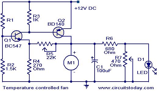
Temperature controlled DC fan
This circuit utilizes two transistors to regulate the speed of a 12 V DC fan based on temperature changes. A thermistor (R1) detects the temperature. As the temperature rises, the base current of transistor Q1 (BC 547) increases, leading to...
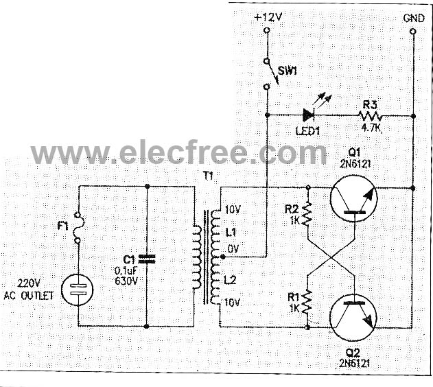
Micro Inverter by 2N6121
This micro inverter is a small-sized device that modifies energy from a battery, producing an output voltage of approximately 220V AC at 50Hz. The circuit comprises two transistors that function as a pulse oscillator or square wave generator, driving a...
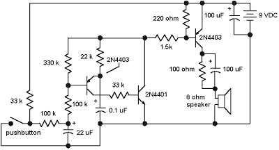
Emergency Siren Simulator
The core of the circuit is a two-transistor flasher, with frequency modulation applied to the base of the first transistor. When the pushbutton is pressed, the oscillation frequency increases to a peak, and upon releasing the button, the frequency decreases...