


Choosing a Low-Noise Amplifier
#low-noise amplifier
#analog applications
#data converters
#strain-gauge
#microphone pre-amplifier
#signal amplification
#low frequency
#operational amplifier
#audio
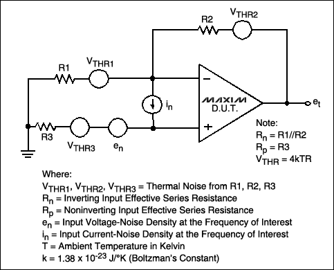
Description: This article examines key parameters in choosing a low noise amplifier for low frequency analog applications such as buffering data converters, amplifying strain-gauge signals, and pre-amplifying microphone outputs.
Low noise amplifiers (LNAs) are critical components in various analog applications that require the amplification of weak signals while minimizing added noise. When selecting an LNA for low frequency applications, several key parameters must be considered to ensure optimal performance.
Firstly, the noise figure (NF) of the amplifier is a crucial metric. It quantifies the degradation of the signal-to-noise ratio (SNR) as the signal passes through the amplifier. A lower NF indicates better performance, as it contributes less noise to the amplified signal. For low frequency applications, an NF of less than 3 dB is generally desirable.
Secondly, the gain of the amplifier must be evaluated. The gain determines how much the input signal will be amplified. It is essential to choose an LNA with sufficient gain to overcome any subsequent stages in the signal chain while avoiding saturation. Typically, a gain range of 20 to 40 dB is suitable for most low frequency applications.
Input and output impedance are also significant factors. The input impedance should match the source impedance to minimize reflections and maximize power transfer. Similarly, the output impedance should be compatible with the load to ensure efficient signal transmission. Commonly, input and output impedances of 50 ohms or 75 ohms are used in many applications.
Another important consideration is the bandwidth of the amplifier. The bandwidth must encompass the frequency range of interest for the specific application. For instance, in buffering data converters, the amplifier should support the Nyquist frequency of the converter to prevent aliasing.
Additionally, power consumption is a critical parameter, especially in battery-operated devices. Selecting an LNA with low quiescent current can enhance battery life while maintaining performance standards.
Thermal stability and linearity are also vital, particularly in applications involving strain gauges and microphones, where signal integrity is paramount. A well-designed LNA should exhibit minimal drift with temperature changes and maintain linearity across its operating range to avoid distortion of the amplified signal.
In summary, selecting an appropriate low noise amplifier for low frequency analog applications necessitates careful consideration of noise figure, gain, impedance matching, bandwidth, power consumption, thermal stability, and linearity. Each of these parameters plays a significant role in ensuring that the amplifier performs effectively in its intended application, thereby enhancing the overall system performance.This article examines key parameters in choosing a low noise amplifier for low frequency analog applications such as buffering data converters, amplifying strain-gauge signals, and pre-amplifying microphone outputs..
Low noise amplifiers (LNAs) are critical components in various analog applications that require the amplification of weak signals while minimizing added noise. When selecting an LNA for low frequency applications, several key parameters must be considered to ensure optimal performance.
Firstly, the noise figure (NF) of the amplifier is a crucial metric. It quantifies the degradation of the signal-to-noise ratio (SNR) as the signal passes through the amplifier. A lower NF indicates better performance, as it contributes less noise to the amplified signal. For low frequency applications, an NF of less than 3 dB is generally desirable.
Secondly, the gain of the amplifier must be evaluated. The gain determines how much the input signal will be amplified. It is essential to choose an LNA with sufficient gain to overcome any subsequent stages in the signal chain while avoiding saturation. Typically, a gain range of 20 to 40 dB is suitable for most low frequency applications.
Input and output impedance are also significant factors. The input impedance should match the source impedance to minimize reflections and maximize power transfer. Similarly, the output impedance should be compatible with the load to ensure efficient signal transmission. Commonly, input and output impedances of 50 ohms or 75 ohms are used in many applications.
Another important consideration is the bandwidth of the amplifier. The bandwidth must encompass the frequency range of interest for the specific application. For instance, in buffering data converters, the amplifier should support the Nyquist frequency of the converter to prevent aliasing.
Additionally, power consumption is a critical parameter, especially in battery-operated devices. Selecting an LNA with low quiescent current can enhance battery life while maintaining performance standards.
Thermal stability and linearity are also vital, particularly in applications involving strain gauges and microphones, where signal integrity is paramount. A well-designed LNA should exhibit minimal drift with temperature changes and maintain linearity across its operating range to avoid distortion of the amplified signal.
In summary, selecting an appropriate low noise amplifier for low frequency analog applications necessitates careful consideration of noise figure, gain, impedance matching, bandwidth, power consumption, thermal stability, and linearity. Each of these parameters plays a significant role in ensuring that the amplifier performs effectively in its intended application, thereby enhancing the overall system performance.This article examines key parameters in choosing a low noise amplifier for low frequency analog applications such as buffering data converters, amplifying strain-gauge signals, and pre-amplifying microphone outputs..

FFT audio amplifier design
For all the subsequent tests, a high-quality signal generator from BlackStar was utilized. The PicoScope trace displayed below illustrates a pure 1 kHz tone from the signal generator. It is important to note that while the screenshots below depict the...

Power AmplifierCircuit and Schematics for 25 Watts-IC TDA2009
Power amplifier circuit diagram with schematics. This simple audio power amplifier circuit is designed for 25 watts output power using TDA 2009 IC, which has two channels (stereo), 12.5 W for each channel.
The described power amplifier circuit utilizes the TDA...

Power Amlifier 40W Class A circuit
This is an audio power amplifier that delivers 40 W at 8 ohms in Class A operation. The power transistors are continuously active, enabling a substantial current to flow.
The audio power amplifier described operates in Class A mode, which is...

The Audionics CC-2 Amplifier
The Audionics CC-2 is named after Cliff Moulton, the chief engineer, and Charles Wood, the president of Audionics. However, the true designer of the amplifier is Bob Sickler, whose initials, "RLS," appear on the schematics. Following Bob's passing in Portland,...

Audio Electronic Locker Circuit Schematic Picture
All the adapted numbers of the cipher are in the aforementioned line. To set the adjustment of the cardinal of the code, we accept to set the acceptable affiliation amid the bulge of the 7414 ascribe and the adapted bulge...

Audio-powered noise clipper
T1 and T2 are 600 to 8-ohm transformers (any transistor radio output transformers with 500 to 4-ohm impedance may be used). Q1 is a 2N2222 NPN transistor, and Q2 is a 2N2907 PNP transistor. D1 and D2 are 1N270 signal...
operational amplifier op amp oscillator
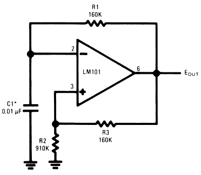
The timing capacitor (C1) generates multiple time constants, facilitating substantial voltage fluctuations at the input, attributable to the LM101's extensive input voltage range. It is advisable to decrease the value of resistor R2 and to increase the capacitance of C1...

Audio MP3 Car Amplifier Schematic Circuits 150W
These accessories are low-cost, high-speed, bifet-input operational amplifiers utilizing internally compensated voltage (BI-FET II technology). They require low supply voltages while offering a wide gain bandwidth product and fast slew rate. Additionally, well-matched high voltage JFET input devices accommodate very...

cut the feed forward in the miller compensation with voltage buffer
An internally compensated operational amplifier has been fabricated using n-channel Al-gate MOS technology, utilizing only enhancement mode devices. The circuit is designed to ensure that its performance remains insensitive to process parameters. The input stage consists of a source-coupled differential...