


Sensitive optical receiver amplifier
#optical receiver
#OPA111
#high gain
#feedback resistor
#sensitive amplifier
#signal transmission
#operational amplifier
#optical signal

Description: The OPA111 optical receiver amplifier features a feedback resistor of 200 MΩ, which is crucial due to the high gain of the amplifier. The OPA111 is designed to receive signals transmitted over optical fiber, specifically at a rate of 9600 baud using Manchester encoding. The amplified output is then fed into a voltage comparator, the LM211, which shapes the signal into standard data signals.
The OPA111 optical receiver amplifier operates effectively in high-gain applications, making it suitable for receiving low-level signals from optical fibers. The choice of a 200 MΩ feedback resistor is significant as it helps maintain the stability of the amplifier while ensuring that the gain remains sufficiently high to amplify the weak optical signals. The OPA111's ability to handle high-frequency signals makes it ideal for applications such as data transmission over fiber optics, where signal integrity is paramount.
Upon receiving the optical signals encoded in Manchester format at a baud rate of 9600, the OPA111 amplifies these signals, compensating for any losses that may occur during transmission through the optical medium. The amplified output signal is then directed to the LM211 voltage comparator, which serves to convert the analog amplified signal into a digital representation. The LM211 is selected for its fast response time and ability to accurately determine the threshold levels, ensuring that the output is a clean and reliable standard data signal suitable for further processing in digital systems.
In summary, the combination of the OPA111 optical receiver amplifier and the LM211 voltage comparator forms a robust circuit for optical signal processing, capable of efficiently handling data transmission in high-speed optical communication systems.FIG sensitive ((InW) .OPA111 optical receiver amplifier feedback resistor of FIG 200Mn, because the gain of the amplifier is high .OPAI11 receiving signals transmitted over an optical fiber (9600 Botemanqie Manchester data), is amplified feeding voltage comparator LM211, shaped into standard data signals.
The OPA111 optical receiver amplifier operates effectively in high-gain applications, making it suitable for receiving low-level signals from optical fibers. The choice of a 200 MΩ feedback resistor is significant as it helps maintain the stability of the amplifier while ensuring that the gain remains sufficiently high to amplify the weak optical signals. The OPA111's ability to handle high-frequency signals makes it ideal for applications such as data transmission over fiber optics, where signal integrity is paramount.
Upon receiving the optical signals encoded in Manchester format at a baud rate of 9600, the OPA111 amplifies these signals, compensating for any losses that may occur during transmission through the optical medium. The amplified output signal is then directed to the LM211 voltage comparator, which serves to convert the analog amplified signal into a digital representation. The LM211 is selected for its fast response time and ability to accurately determine the threshold levels, ensuring that the output is a clean and reliable standard data signal suitable for further processing in digital systems.
In summary, the combination of the OPA111 optical receiver amplifier and the LM211 voltage comparator forms a robust circuit for optical signal processing, capable of efficiently handling data transmission in high-speed optical communication systems.FIG sensitive ((InW) .OPA111 optical receiver amplifier feedback resistor of FIG 200Mn, because the gain of the amplifier is high .OPAI11 receiving signals transmitted over an optical fiber (9600 Botemanqie Manchester data), is amplified feeding voltage comparator LM211, shaped into standard data signals.

Cosine wave Oscillator
This circuit is designed to output both a sine wave and a cosine wave. The design utilizes an operational amplifier, with the output frequency determined by component values set to 1Hz. The first operational amplifier generates a 1Hz sine wave,...

Class A Modular Preamplifier with Single Integrated Circuit
The circuit is based on a single operational amplifier integrated circuit designed to produce a modular preamplifier that operates in Class A configuration.
The modular preamplifier circuit utilizes a single operational amplifier (op-amp) integrated circuit, which serves as the primary amplification...

Homemade whole integrated circuit amplifiers 01
The circuit depicted in Figure 5-60 and Figure 6 utilizes an operational amplifier (op-amp) configured as a channel pre-amplifier to address the signal loss introduced by the tone control circuit. Additionally, another group of op-amps forms a channel-driven stage amplifier...

cut the feed forward in the miller compensation with voltage buffer
An internally compensated operational amplifier has been fabricated using n-channel Al-gate MOS technology, utilizing only enhancement mode devices. The circuit is designed to ensure that its performance remains insensitive to process parameters. The input stage consists of a source-coupled differential...

Buffer leakage current measurement circuit diagram OPA111 INA117
The circuit illustrated in FIG OPA111 is designed for measuring input buffer leakage current. The transistors D1 and D2, which are 2N3904 types, short the base and collector contacts while leaving the emitter open. When a power supply of up...

X10 operational amplifier
The amplifier is 3 dB down at 100 kHz and has a slew rate of 0.02 V/µs.
The amplifier's performance characteristics indicate that it experiences a 3 dB attenuation at a frequency of 100 kHz. This specification suggests that at this...

X100 operational amplifier
The amplifier has a gain-bandwidth product of 20 MHz, with a slew rate of 0.3 V/µs.
The amplifier's gain-bandwidth product (GBP) of 20 MHz indicates that the product of the amplifier's gain and the bandwidth at which that gain is applicable...
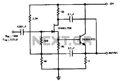
High gain amplifier circuit
The 2N5485, which has a very low-capacity legacy, is always operated as a source follower with gate bias bootstrap. In this circuit, nothing is left to chance in reducing input capacitance.
The 2N5485 is a JFET (Junction Field Effect Transistor) known...

Operational-amplifiers
This is a single gain-of-100 amplifier with a gain-bandwidth product of 20 MHz. The primary limitation in performance is the low slew rate of 0.3 V/μs imposed by the charging of Ccomp. The effects of slew rate and compensation are...