


Two-stage wideband amplifier

Description: A wideband high gain configuration using two SL550s connected in series. The first stage is connected in a common emitter configuration, while the second stage is a common base circuit. Stable gains of up to 65 dB can be achieved by the proper choice of Rl and R2. The bandwidth ranges from 5 to 130 MHz, with a noise figure only marginally greater than the 2 dB specified for a single-stage circuit.
The described circuit utilizes two SL550 transistors to create a high-gain amplifier configuration. The first stage, configured as a common emitter amplifier, provides voltage amplification and is characterized by its high input impedance and low output impedance. This configuration is effective for providing significant gain, which is essential for applications requiring amplification of weak signals.
The second stage operates in a common base configuration, which is advantageous for its low input impedance and high output impedance characteristics. This stage is particularly effective in enhancing bandwidth while maintaining stability and linearity. The combination of these two configurations allows for a broad operational bandwidth from 5 MHz to 130 MHz, making it suitable for various RF applications.
The selection of resistors Rl (load resistor) and R2 (emitter resistor) is critical in achieving the desired gain of up to 65 dB. Proper values for these resistors will ensure optimal performance of the amplifier, balancing gain with stability and minimizing distortion. The low noise figure, marginally exceeding 2 dB, indicates that this configuration is capable of maintaining a high signal-to-noise ratio, which is crucial in communication systems where signal integrity is paramount.
Overall, this wideband amplifier configuration is well-suited for applications in telecommunications, signal processing, and other areas where high gain and bandwidth are essential. Its design effectively leverages the characteristics of both common emitter and common base stages to deliver reliable performance in demanding environments.A wideband high gain configuration using two SL550s connected in series. The first stage is connected in common emitter configuration, the second stage is a common base circuit. Stable gains of up to 65 dB can be achieved by the proper choice of Rl and R2 The bandwidth is 5 to 130 MHz, with a noise figure only marginally greater than the 2 dB specified for a single stage circuit.
The described circuit utilizes two SL550 transistors to create a high-gain amplifier configuration. The first stage, configured as a common emitter amplifier, provides voltage amplification and is characterized by its high input impedance and low output impedance. This configuration is effective for providing significant gain, which is essential for applications requiring amplification of weak signals.
The second stage operates in a common base configuration, which is advantageous for its low input impedance and high output impedance characteristics. This stage is particularly effective in enhancing bandwidth while maintaining stability and linearity. The combination of these two configurations allows for a broad operational bandwidth from 5 MHz to 130 MHz, making it suitable for various RF applications.
The selection of resistors Rl (load resistor) and R2 (emitter resistor) is critical in achieving the desired gain of up to 65 dB. Proper values for these resistors will ensure optimal performance of the amplifier, balancing gain with stability and minimizing distortion. The low noise figure, marginally exceeding 2 dB, indicates that this configuration is capable of maintaining a high signal-to-noise ratio, which is crucial in communication systems where signal integrity is paramount.
Overall, this wideband amplifier configuration is well-suited for applications in telecommunications, signal processing, and other areas where high gain and bandwidth are essential. Its design effectively leverages the characteristics of both common emitter and common base stages to deliver reliable performance in demanding environments.A wideband high gain configuration using two SL550s connected in series. The first stage is connected in common emitter configuration, the second stage is a common base circuit. Stable gains of up to 65 dB can be achieved by the proper choice of Rl and R2 The bandwidth is 5 to 130 MHz, with a noise figure only marginally greater than the 2 dB specified for a single stage circuit.

Wideband Amplifier
This wideband amplifier utilizes a MAR1 integrated circuit (IC), functioning as a gain block. The device is produced by Mini-Circuits Lab and provides a gain of +13 dB from DC to 1000 MHz. The load resistor (Rl) is chosen to...

How to calculate the resistors and capacitors for an amplifier circuit
The circuit above is a canonical AC coupled common emitter amplifier, which is typically used as a linear amplifier rather than a switch that activates when the input exceeds a certain level.
The AC coupled common emitter amplifier is a...

Miniature Wideband Amplifier Circuit
Except for the coupling and decoupling capacitors, IC1 is a complete wideband amplifier that has a fixed gain of 20 dB up to 450 MHz. No external compensation is required. Since the NE5205 functions as a gain block, two or...

Turn A Compensated Current Sink Into A Common Emitter (CE) Amplifier
By adding only a few components, a temperature- and beta-compensated current sink can be converted into a common-emitter (CE) amplifier that maintains a stable biased operating point. This design concept will demonstrate the process.
To implement this design, the primary goal...
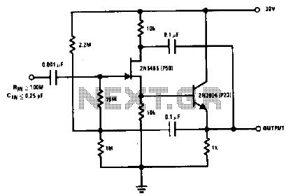
High gain amplifier circuit
The 2N5485, which has a very low-capacity legacy, is always operated as a source follower with gate bias bootstrap. In this circuit, nothing is left to chance in reducing input capacitance.
The 2N5485 is a JFET (Junction Field Effect Transistor) known...

TALKING ELECTRONICS BEC
This circuit is easily identifiable by three equal-value capacitors and two equal-value resistors connected to the base of the transistor. The output signal of a transistor in COMMON EMITTER mode is FALLING when the input signal is RISING, which results...

F733 integrated amplifiers common emitter - common base wideband amplifier circuit
The F733 integrated wideband amplifier is a common-emitter configuration that features a total wideband amplifier with an internal feedback circuit. It is compact, offers zoom capability, and exhibits excellent circuit stability. The F733 circuit, as illustrated in the accompanying figure,...

wideband output amplifier circuit
This design outlines a simple wideband output amplifier suitable for use as a 50-ohm transmission line driver. The circuit is constructed using the CA3140 operational amplifier. When utilized alongside the function generator and sine wave shaper circuits, it delivers an...