


Balanced Line Driver & Receiver
#balanced line
#unbalanced input
#unbalanced output
#hi-fi
#phantom feed
#differential feed
#audio signal
#line driver
#line receiver

Description: With this simple project, you can have balanced lines too, simply adapting the unbalanced inputs and outputs of your hi-fi gear to become balanced, and then back to unbalanced at the other end. You can even be extra cunning, and power the remote converter from the cables carrying the signal. Professionally, this is called "Phantom Feed", and is used to power microphones and other low current equipment. The version I have shown is actually a differential feed. Whilst not as good as a true 48V phantom powering circuit, it does work, and makes an interesting experiment (if nothing else). More: Before we start, a brief description of the standard (unbalanced) and balanced line is in order. An unbalanced line is the type you have on the hi-fi, typically using an RCA connector, and feeding the signal through a coaxial cable. The inner cable carries the signal.
This project involves the conversion of unbalanced audio signals to balanced signals, which is beneficial for reducing noise and interference over long cable runs. The circuit can be implemented using operational amplifiers (op-amps) configured to create a differential signal from the unbalanced input. The unbalanced signal, typically carried over an RCA connector, is fed into an op-amp circuit where it is transformed into a balanced output suitable for XLR connectors.
The balanced line consists of two conductors carrying the same audio signal but with opposite polarity. This configuration allows the receiving end to reject any noise that may have been picked up along the cable, as the noise will likely affect both lines equally and can be canceled out. The circuit can also include a phantom power feature, which allows the remote device to be powered directly through the audio cables. This is achieved by injecting a low voltage DC signal, typically around 48V, onto the balanced lines, which can then be extracted by the microphone or other low-current devices at the receiving end.
For the implementation, the circuit design will include the following components:
1. Two op-amps for differential amplification.
2. Resistors to set the gain and balance the circuit.
3. Capacitors for filtering and stability.
4. A power supply circuit to provide the necessary voltage for the op-amps and phantom power.
The design should ensure that the op-amps are configured correctly to minimize distortion and maintain audio fidelity. The use of high-quality components is recommended to achieve optimal performance. Additionally, proper grounding techniques should be employed to further reduce noise and interference.
In conclusion, this project provides a practical solution for converting unbalanced audio signals to balanced lines, with the added capability of phantom powering, making it an excellent experiment for audio enthusiasts and professionals alike.With this simple project, you can have balanced lines too, simply adapting the unbalanced inputs and outputs of your hi-fi gear to become balanced, and then back to unbalanced at the other end. You can even be extra cunning, and power the remote converter from the cables carrying the signal. Professionally, this is called "Phantom Feed", and is used to power microphones and other low current equipment.
The version I have shown is actually a differential feed. Whilst not as good as a true 48V phantom powering circuit, it does work, and makes an interesting experiment (if nothing else). Before we start, a brief description of the standard (unbalanced) and balanced line is in order. An unbalanced line is the type you have on the hi-fi, typically using an RCA connector, and feeding the signal through a coaxial cable. The inner cable carrie
This project involves the conversion of unbalanced audio signals to balanced signals, which is beneficial for reducing noise and interference over long cable runs. The circuit can be implemented using operational amplifiers (op-amps) configured to create a differential signal from the unbalanced input. The unbalanced signal, typically carried over an RCA connector, is fed into an op-amp circuit where it is transformed into a balanced output suitable for XLR connectors.
The balanced line consists of two conductors carrying the same audio signal but with opposite polarity. This configuration allows the receiving end to reject any noise that may have been picked up along the cable, as the noise will likely affect both lines equally and can be canceled out. The circuit can also include a phantom power feature, which allows the remote device to be powered directly through the audio cables. This is achieved by injecting a low voltage DC signal, typically around 48V, onto the balanced lines, which can then be extracted by the microphone or other low-current devices at the receiving end.
For the implementation, the circuit design will include the following components:
1. Two op-amps for differential amplification.
2. Resistors to set the gain and balance the circuit.
3. Capacitors for filtering and stability.
4. A power supply circuit to provide the necessary voltage for the op-amps and phantom power.
The design should ensure that the op-amps are configured correctly to minimize distortion and maintain audio fidelity. The use of high-quality components is recommended to achieve optimal performance. Additionally, proper grounding techniques should be employed to further reduce noise and interference.
In conclusion, this project provides a practical solution for converting unbalanced audio signals to balanced lines, with the added capability of phantom powering, making it an excellent experiment for audio enthusiasts and professionals alike.With this simple project, you can have balanced lines too, simply adapting the unbalanced inputs and outputs of your hi-fi gear to become balanced, and then back to unbalanced at the other end. You can even be extra cunning, and power the remote converter from the cables carrying the signal. Professionally, this is called "Phantom Feed", and is used to power microphones and other low current equipment.
The version I have shown is actually a differential feed. Whilst not as good as a true 48V phantom powering circuit, it does work, and makes an interesting experiment (if nothing else). Before we start, a brief description of the standard (unbalanced) and balanced line is in order. An unbalanced line is the type you have on the hi-fi, typically using an RCA connector, and feeding the signal through a coaxial cable. The inner cable carrie

60-100W Hi-Fi Power Amplifier
The output devices are MJL4281A (NPN) and MJL4302A (PNP), and feature high bandwidth, excellent SOA (safe operating area), high linearity and high gain. Driver transistors are MJE15034 (NPN) and MJE15035 (PNP). All devices are rated at 350V, with the power...

Hi-Fi Preamplifier
Cleaned Input: The circuit was submitted by an individual from Newtownabbey, Northern Ireland. It has an exceptionally fast high frequency response, as demonstrated by applying a 100kHz squarewave to the input. All graphs were produced using Tina Pro.
The circuit in...

Hi-Fi power amplifier with MJ3001 and MJ2501
This is a very simple, low cost, Hi-Fi quality power amplifier. You can build it 5 ways, like it is shown in the table (from 20 W to 80 W RMS). The first thing that you must do, is to...

The many ideas of 100 watt amplifier circuit
The power amplifier Hi-Fi OCL 120W RMS is designed to operate effectively when paired with a suitable power supply circuit and 8-ohm speakers. This circuit exclusively utilizes transistors without any integrated circuits, resulting in a clean sound output. The recommended...

Hi-Fi Phono Preamp (RIAA Equalisation)
The schematic in question pertains to a phono preamplifier that is characterized by an accurate RIAA equalisation curve. Notably, this preamplifier boasts superior sonic performance compared to most others featured in magazines and application notes. This preamplifier, much like other...
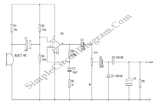
Audio Signal Strength Detector/Converter
Below is the schematic diagram of an audio input module. This module is capable of producing a DC output voltage that is proportional to the amplitude of the input signal.
The audio input module typically consists of several key components that...

2x150W no large loop feedback hi-fi amplifier
It is widely recognized that while a large loop feedback from the amplifier output stage to the preceding stage can enhance frequency response and reduce harmonic distortion indicators in an amplifier, it may adversely affect the transient characteristics and certain...

Hi-Fi Preamplifier Circuit Project
This circuit exhibits an exceptionally fast high-frequency response, as demonstrated by applying a 100 kHz square wave to the input. All graphs were produced using Tina Pro.
The circuit's design is optimized for high-frequency applications, showcasing rapid response times that are...

Construction of 50Watt 8Ω two-way Hi-Fi Speakers
The speakers presented are notable for their compact size and exceptional sound quality. Often, home spaces are limited, making large speakers impractical. However, this does not imply a compromise on sound quality. The design is straightforward, cost-effective, and easy to...