


mini audio analyzer
#audio analyzer
#frequency analysis
#LED visualization
#acoustic signal
#sound measurement
#signal width
#frequency response
#audio processing
#sensitive instrument
#visual feedback
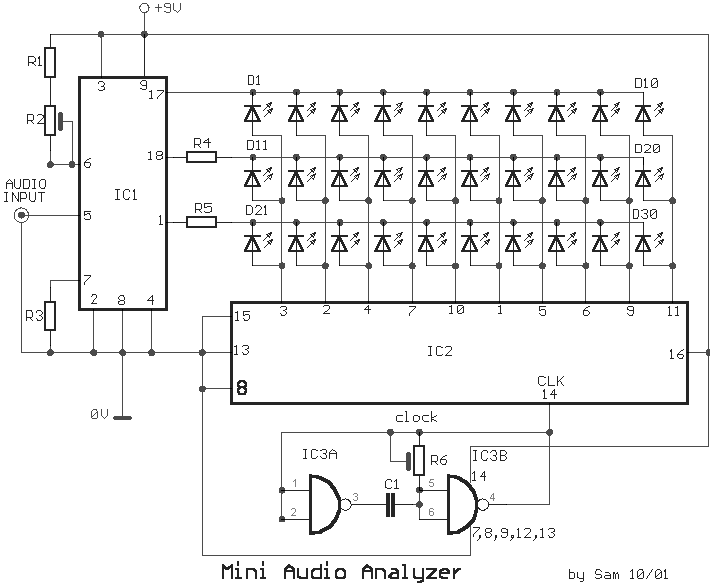
Description: This device is a sensitive instrument that detects frequency changes and the width of an acoustic signal. The brightness of the LED that activates at each moment is proportional to the signal width, while the color corresponds to the frequency.
The circuit described operates as an acoustic signal analyzer, utilizing an LED as a visual output to represent the characteristics of the incoming signal. The core components of the circuit include a microphone or piezoelectric sensor to capture the acoustic signals, an analog-to-digital converter (ADC) for digital signal processing, and a microcontroller to interpret the signal data.
The microphone converts sound waves into electrical signals, which are then fed into the ADC. The ADC samples the analog signal and converts it into a digital format that can be processed by the microcontroller. The microcontroller analyzes the digital signal to determine both the frequency and the width of the signal.
To represent the signal width, the microcontroller adjusts the brightness of the LED. This is achieved through pulse-width modulation (PWM), where the duty cycle of the PWM signal controls the average power delivered to the LED. A wider signal translates to a higher duty cycle, resulting in increased brightness.
For frequency representation, the microcontroller may use a color LED or a multi-color LED that can change color based on the frequency detected. By mapping specific frequency ranges to corresponding colors, the system provides a visual representation of the frequency content of the acoustic signal.
This circuit can have applications in various fields such as audio engineering, sound analysis, and educational tools for demonstrating acoustic principles. Proper calibration and tuning of the circuit are essential to ensure accurate representation of the signal characteristics, which can be achieved through adjustments in the software algorithms and hardware components.This analyst is, a sensitive instrument, in the frequency changes and width of a acoustic signal. Thus the brightness of LED that turns on each moment of is proportional signal width, while the colour of proportionally frequency..
The circuit described operates as an acoustic signal analyzer, utilizing an LED as a visual output to represent the characteristics of the incoming signal. The core components of the circuit include a microphone or piezoelectric sensor to capture the acoustic signals, an analog-to-digital converter (ADC) for digital signal processing, and a microcontroller to interpret the signal data.
The microphone converts sound waves into electrical signals, which are then fed into the ADC. The ADC samples the analog signal and converts it into a digital format that can be processed by the microcontroller. The microcontroller analyzes the digital signal to determine both the frequency and the width of the signal.
To represent the signal width, the microcontroller adjusts the brightness of the LED. This is achieved through pulse-width modulation (PWM), where the duty cycle of the PWM signal controls the average power delivered to the LED. A wider signal translates to a higher duty cycle, resulting in increased brightness.
For frequency representation, the microcontroller may use a color LED or a multi-color LED that can change color based on the frequency detected. By mapping specific frequency ranges to corresponding colors, the system provides a visual representation of the frequency content of the acoustic signal.
This circuit can have applications in various fields such as audio engineering, sound analysis, and educational tools for demonstrating acoustic principles. Proper calibration and tuning of the circuit are essential to ensure accurate representation of the signal characteristics, which can be achieved through adjustments in the software algorithms and hardware components.This analyst is, a sensitive instrument, in the frequency changes and width of a acoustic signal. Thus the brightness of LED that turns on each moment of is proportional signal width, while the colour of proportionally frequency..

Arduino Vocal Effects Box
This Arduino-powered vocal effects box pitch shifts and distorts incoming audio signals to produce a wide variety of vocal effects. This project is an experiment with real-time digital signal processing using Arduino. It samples an incoming microphone signal at a...

4047/4066 audio slicer
You need to connect pins 1 and 13 of the 4053 to the virtual ground rail (top of C4), not the circuit's 0V rail.
The CD4053 is a triple 2-channel analog multiplexer/demultiplexer integrated circuit, widely used for routing analog signals...

Audio Beat Detect ?« Electronic Product Design
This circuit employs a digital potentiometer to enable the microcontroller to automatically adjust the circuit's gain according to the ambient audio volume. However, a standard potentiometer can be used if automatic adjustment is unnecessary. The low-pass filter design is based...
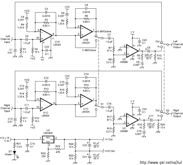
ARRL Handbook Audio Intelligibility Enhancer
Assistance is sought for building the N4GG audio intelligibility enhancer project as detailed in the ARRL Handbook. A circuit board has been ordered from Far Circuits, but there are difficulties in sourcing the necessary components. Attempts have been made to...

mini audio analyzer
This instrument is a sensitive analyzer that detects changes in frequency and the width of an acoustic signal. The brightness of the LED that activates at any given moment is proportional to the width of the signal, while the color...

Central-image-canceller
The circuit is designed to eliminate the vocal portion of an audio signal while preserving the instrumental portion. It achieves this by mixing two channels that are 180° out of phase, allowing the signals that create the center-stereo image to...