


Passive Filter Circuits
#passive filter
#low pass filter
#high pass filter
#signal processing
#filter circuits
#electronics
#frequency response
#RC filter
#audio electronics
#component selection
Description: This guide aims to demonstrate the construction of various filter circuits, specifically low pass and high pass filters, along with additional details.
The construction of filter circuits is essential in many electronic applications, as they allow for the selective passage of signals based on frequency. Low pass filters (LPF) enable signals with a frequency lower than a certain cutoff frequency to pass through while attenuating higher frequencies. Conversely, high pass filters (HPF) permit signals with frequencies higher than a specific cutoff frequency to pass while blocking lower frequencies.
A typical low pass filter can be designed using passive components such as resistors and capacitors (RC filter). The simplest form consists of a resistor (R) connected in series with the input signal and a capacitor (C) connected in parallel to the output. The cutoff frequency (fc) is determined by the formula:
fc = 1 / (2πRC)
For example, if a resistor of 1 kΩ is used in conjunction with a capacitor of 100 nF, the cutoff frequency would be approximately 1.59 kHz.
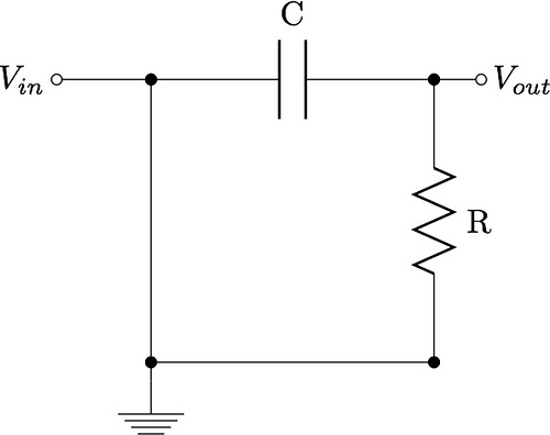
On the other hand, a high pass filter can also be constructed using an RC configuration, but with the capacitor placed in series with the input signal and the resistor connected to the ground. The cutoff frequency for a high pass filter is also given by the same formula:
fc = 1 / (2πRC)
In this configuration, the same resistor and capacitor values would yield the same cutoff frequency, but the behavior of the circuit would be opposite, allowing frequencies above the cutoff to pass while attenuating those below it.
In addition to the basic RC filters, more complex filter designs such as active filters using operational amplifiers can be implemented to achieve sharper roll-offs and better performance characteristics. Active filters can provide gain, improve input impedance, and reduce the effects of component tolerances.
Overall, understanding and implementing low pass and high pass filters is fundamental for engineers and hobbyists working with signal processing, audio applications, and communication systems. Proper design and analysis of these filters are crucial for achieving desired performance in various electronic circuits.This instructable is intended to show you how to make several different filter circuits, in particular, low pass and high pass filters, along with a..
The construction of filter circuits is essential in many electronic applications, as they allow for the selective passage of signals based on frequency. Low pass filters (LPF) enable signals with a frequency lower than a certain cutoff frequency to pass through while attenuating higher frequencies. Conversely, high pass filters (HPF) permit signals with frequencies higher than a specific cutoff frequency to pass while blocking lower frequencies.
A typical low pass filter can be designed using passive components such as resistors and capacitors (RC filter). The simplest form consists of a resistor (R) connected in series with the input signal and a capacitor (C) connected in parallel to the output. The cutoff frequency (fc) is determined by the formula:
fc = 1 / (2πRC)
For example, if a resistor of 1 kΩ is used in conjunction with a capacitor of 100 nF, the cutoff frequency would be approximately 1.59 kHz.
On the other hand, a high pass filter can also be constructed using an RC configuration, but with the capacitor placed in series with the input signal and the resistor connected to the ground. The cutoff frequency for a high pass filter is also given by the same formula:
fc = 1 / (2πRC)
In this configuration, the same resistor and capacitor values would yield the same cutoff frequency, but the behavior of the circuit would be opposite, allowing frequencies above the cutoff to pass while attenuating those below it.
In addition to the basic RC filters, more complex filter designs such as active filters using operational amplifiers can be implemented to achieve sharper roll-offs and better performance characteristics. Active filters can provide gain, improve input impedance, and reduce the effects of component tolerances.
Overall, understanding and implementing low pass and high pass filters is fundamental for engineers and hobbyists working with signal processing, audio applications, and communication systems. Proper design and analysis of these filters are crucial for achieving desired performance in various electronic circuits.This instructable is intended to show you how to make several different filter circuits, in particular, low pass and high pass filters, along with a..

RC filters-operation-circuit-diagram
The disadvantages of pi-filters include higher costs, increased weight, larger size, and the external magnetic field generated by the series inductor. These issues can be mitigated by substituting the series inductor with a series resistor, referred to as an R-C...

Low pass filter for subwoofer
Several low-pass filter circuits for subwoofers are presented here, and this is another example. The circuit is based on the TL062 op-amp from ST Microelectronics. The TL062 is a dual high-input impedance J-FET op-amp that exhibits very low power consumption...

Filter
Several low-pass filter circuits for subwoofers are presented here, including this particular design. The circuit utilizes the TL062 operational amplifier from ST Microelectronics. The TL062 is a dual high-input impedance J-FET operational amplifier that features low power consumption and a...
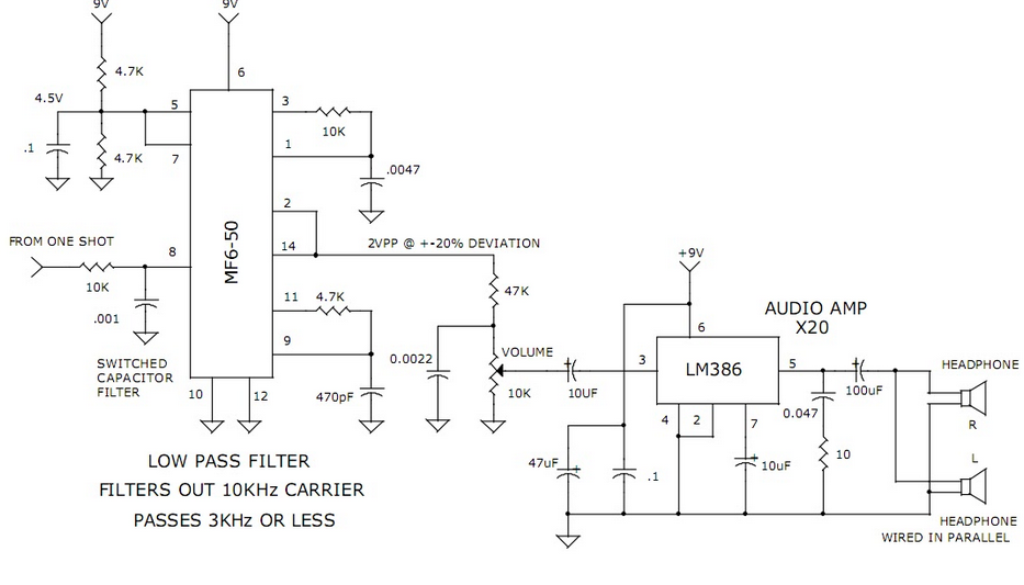
3khz Low Pass Filter and Audio Amplifier
This circuit utilizes a switched capacitor filter integrated circuit (IC) from National Semiconductor to filter signals with frequencies exceeding 3 kHz, which are not required for voice audio.
The circuit design incorporates a switched capacitor filter IC, which is a pivotal...

The same capacitance parameters easy to change the cutoff frequency of the low pass filter 24dB-oct
A 24 dB/octave Butterworth filter with a maximally flat characteristic is constructed using two filters, each capable of providing a 12 dB/octave response. This configuration allows for a 3 dB point adjustment. To achieve the desired cutoff frequency, adjustments are...

Multiple feedback low pass filter
The low bias currents allow for the utilization of high resistance and low capacitance values, facilitating a low frequency cutoff at fc = 10 Hz, with an AVCL of 4 and a passband ripple of 0.1 dB. Additionally, small capacitors...

gcr
A 5-pole elliptic low pass filter (impedance: 50 Ohm, -6 dB cutoff frequency 33 MHz) connects the antenna signal to the diode ring mixer, a traditional SBL-1, which performs well even below 500 kHz. A high pass/low pass diplexing filter...
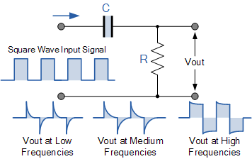
High Pass Filter Tutorial
Electronics tutorial about passive high pass filter circuit, including passive RC high pass filter first order frequency response, Bode plot, and construction.
The passive high pass filter circuit is an essential component in electronics, designed to allow signals with a frequency...

Passive tone control circuit
The passive tone control circuit is designed to adjust the bass without expansion, utilizing resistors (R) and capacitors (C). It functions as a frequency filter and is easy to construct, requiring no external power supply. This circuit can be connected...