


Second-audio-program-adapter
#audio adapter
#bandpass filter
#quadrature detector
#FM radio
#i-f amplifier
#CA3089
#78.6 kHz
#phase shift
#stereo decoder

Description: The baseband audio input originates from the pole of switch S1 in the stereo decoder and is coupled to IC1 (a CA3089) via a 78.6 kHz bandpass filter composed of capacitors C1 and C2, along with inductor L1. IC1 functions as a combination intermediate frequency (i-f) amplifier and quadrature detector, typically utilized in FM radio systems that operate at an i-f of 10.7 MHz; however, it is also effective at 78.6 kHz. Capacitors C6 and C7, as well as inductor L2, are employed to tune the detector section to 78.6 kHz, while capacitor C5 provides the essential 90-degree phase shift necessary for the proper operation of the quadrature detector.
The output voltage at pin 13 of IC1 is proportional to the incoming signal level. When the voltage at the wiper of potentiometer R3 reaches a specific threshold level, transistor Q1 conducts, grounding pin 5 of IC1 and activating the mute function of IC1. The detected audio output from pin 6 of IC1 is directed to IC2a, which is configured as a low-pass filter with a cutoff frequency of 12 kHz and a roll-off of -12 dB per octave. The output from IC2a is available across potentiometer R10, which allows for adjustment of the drive level into IC3b, the 2:1 compander. The audio signal from the wiper of R10 is divided into two pathways: a high-pass filter formed by C14 and R8 directs the signal to the rectifier input of the compander, while a bandpass filter comprising R9, C16, and C15 feeds the audio input of the compander. A fixed 390 µs de-emphasis network is created using C18 and R11 in conjunction with IC3b. The corrected audio output can be found at pin 10 of IC3b, which is then coupled to IC2b, the output buffer amplifier. Additionally, audio from pin 6 of IC1 is sent through an audio high-pass filter consisting of R5 and C10 before being routed to an audio rectifier composed of diodes D1 and D2, along with capacitor C11. When a Secondary Audio Program (SAP) signal is detected by IC1, it is rectified by D1 and D2, resulting in the discharge of C11. An increasing positive voltage at the base of transistor Q2 leads to a decrease in its current flow, subsequently lowering the voltage at Q2's collector. This drop in voltage causes the base voltage of Q3 to fall, resulting in Q3 conducting and illuminating the LED.
The circuit described operates effectively to process audio signals, utilizing various filtering and amplification stages to achieve the desired output. The CA3089 integrated circuit serves as a versatile component within this audio processing framework, allowing for the detection and amplification of signals at a lower frequency than its typical application in FM radio. The incorporation of filters ensures that only the necessary frequency components are passed through while attenuating unwanted noise. The use of potentiometers for level adjustment provides flexibility in the audio output, enabling fine-tuning based on the specific requirements of the application. Furthermore, the inclusion of a de-emphasis network and compander enhances audio quality by addressing dynamic range and frequency response, making this circuit suitable for a range of audio processing tasks. The LED indicator provides a visual cue for the presence of a SAP signal, enhancing user interaction and feedback. Overall, this circuit exemplifies a comprehensive approach to audio signal processing, integrating various electronic components to achieve effective results.The baseband-audio input comes from the pole of switch Sl in the stereo decoder, and is coupled to IC1 (a CA3089) via a 78.6 kHz bandpass filter that consists of capacitors Cl and C2, and inductor Ll. IC1 is a combination i-f amplifier and quadrature detector normally used for FM radio systems operating within an i-f of 10.7 MHz.
The device works equally well at 78.6 kHz. Capacitors C6 and C7, and inductor L2 tune the detector section to 78.6 kHz, while C5 provides the necessary 90-degree phase shift for proper quadrature detector operation. The output voltage at pin 13 of IC1 is proportional to the level of the incoming signal. When the voltage at the wiper of potentiometer R3 reaches a predetermined threshold level, Ql conducts, grounding pin 5 ofIC1, enabling IC1"s mute function. Detected audio output from pin 6 of IC1 goes to IC2a, which is configured as a 12-kHz, -12 dB per octave, low-pass filter.
The output of IC2a appears across potentiometer RlO, which provides a means of adjusting the drive level into IC3b, the 2:1 compander. Audio from the wiper of RlO is split into two paths: a high-pass filter (C14 and R8) provides a path to the rectifier input of the compander, and a bandpass filter (R9, C16, and C15) that feeds the audio input of the compander.
A fixed 390-~ts de-emphasis network is formed by C18 and Rll in conjunction with IC3b. Corrected audio appears at pin 10 of IC3b and is coupled to IC2b, and output buffer amplifier. Audio from pin 6 of IC1 is also coupled to an audio high-pass filter, R5 and ClO, and fed to an audio rectifier, Dl, D2, and Cll. When a SAP signal is detected by IC1, it is rectified by D1 and D2; the resultant de charges Cll. An increasing positive voltage at the base of Q2 causes its current flow to decrease, so the voltage at Q2"s collector also decreases.
That in tum causes the base voltage of Q3 to drop, which causes Q3 to conduct, thereby lighting the LED.
The output voltage at pin 13 of IC1 is proportional to the incoming signal level. When the voltage at the wiper of potentiometer R3 reaches a specific threshold level, transistor Q1 conducts, grounding pin 5 of IC1 and activating the mute function of IC1. The detected audio output from pin 6 of IC1 is directed to IC2a, which is configured as a low-pass filter with a cutoff frequency of 12 kHz and a roll-off of -12 dB per octave. The output from IC2a is available across potentiometer R10, which allows for adjustment of the drive level into IC3b, the 2:1 compander. The audio signal from the wiper of R10 is divided into two pathways: a high-pass filter formed by C14 and R8 directs the signal to the rectifier input of the compander, while a bandpass filter comprising R9, C16, and C15 feeds the audio input of the compander. A fixed 390 µs de-emphasis network is created using C18 and R11 in conjunction with IC3b. The corrected audio output can be found at pin 10 of IC3b, which is then coupled to IC2b, the output buffer amplifier. Additionally, audio from pin 6 of IC1 is sent through an audio high-pass filter consisting of R5 and C10 before being routed to an audio rectifier composed of diodes D1 and D2, along with capacitor C11. When a Secondary Audio Program (SAP) signal is detected by IC1, it is rectified by D1 and D2, resulting in the discharge of C11. An increasing positive voltage at the base of transistor Q2 leads to a decrease in its current flow, subsequently lowering the voltage at Q2's collector. This drop in voltage causes the base voltage of Q3 to fall, resulting in Q3 conducting and illuminating the LED.
The circuit described operates effectively to process audio signals, utilizing various filtering and amplification stages to achieve the desired output. The CA3089 integrated circuit serves as a versatile component within this audio processing framework, allowing for the detection and amplification of signals at a lower frequency than its typical application in FM radio. The incorporation of filters ensures that only the necessary frequency components are passed through while attenuating unwanted noise. The use of potentiometers for level adjustment provides flexibility in the audio output, enabling fine-tuning based on the specific requirements of the application. Furthermore, the inclusion of a de-emphasis network and compander enhances audio quality by addressing dynamic range and frequency response, making this circuit suitable for a range of audio processing tasks. The LED indicator provides a visual cue for the presence of a SAP signal, enhancing user interaction and feedback. Overall, this circuit exemplifies a comprehensive approach to audio signal processing, integrating various electronic components to achieve effective results.The baseband-audio input comes from the pole of switch Sl in the stereo decoder, and is coupled to IC1 (a CA3089) via a 78.6 kHz bandpass filter that consists of capacitors Cl and C2, and inductor Ll. IC1 is a combination i-f amplifier and quadrature detector normally used for FM radio systems operating within an i-f of 10.7 MHz.
The device works equally well at 78.6 kHz. Capacitors C6 and C7, and inductor L2 tune the detector section to 78.6 kHz, while C5 provides the necessary 90-degree phase shift for proper quadrature detector operation. The output voltage at pin 13 of IC1 is proportional to the level of the incoming signal. When the voltage at the wiper of potentiometer R3 reaches a predetermined threshold level, Ql conducts, grounding pin 5 ofIC1, enabling IC1"s mute function. Detected audio output from pin 6 of IC1 goes to IC2a, which is configured as a 12-kHz, -12 dB per octave, low-pass filter.
The output of IC2a appears across potentiometer RlO, which provides a means of adjusting the drive level into IC3b, the 2:1 compander. Audio from the wiper of RlO is split into two paths: a high-pass filter (C14 and R8) provides a path to the rectifier input of the compander, and a bandpass filter (R9, C16, and C15) that feeds the audio input of the compander.
A fixed 390-~ts de-emphasis network is formed by C18 and Rll in conjunction with IC3b. Corrected audio appears at pin 10 of IC3b and is coupled to IC2b, and output buffer amplifier. Audio from pin 6 of IC1 is also coupled to an audio high-pass filter, R5 and ClO, and fed to an audio rectifier, Dl, D2, and Cll. When a SAP signal is detected by IC1, it is rectified by D1 and D2; the resultant de charges Cll. An increasing positive voltage at the base of Q2 causes its current flow to decrease, so the voltage at Q2"s collector also decreases.
That in tum causes the base voltage of Q3 to drop, which causes Q3 to conduct, thereby lighting the LED.

FM radio tuning circuit circuit
The FM radio circuit consists of a high-frequency amplifier (VT1), a mixer and local oscillator (VT2), and additional components. The circuit includes an FM radio antenna for signal detection, with an input transformer (L1) connected to a gate transistor (VT1),...

audio bandpass filter
The audio bandpass filter described is beneficial for amplifying and filtering weak AM TV video carriers. For instance, a digital frequency audio multimeter (DFM) may lack sufficient input sensitivity for measuring extremely weak single sideband (SSB) TV video audio signals....

FM Crystal Radio Receivers
The concept of a "crystal radio" is typically linked with large antennas and radio broadcasting on long and medium bands. This article discusses experimentally tested detector circuits for VHF receivers designed to listen to FM stations. The discovery of the...

Razor-sharp CW filter
The circuit consists of four stages of active bandpass filtering provided by two type-µ integrated-circuit dual op-amps and includes a simple threshold detector (diodes D1 and D2) between stages 2 and 3 to reduce low-level background noise. Each of the...

RAZOR SHARP CW FILTER
The circuit comprises four stages of active bandpass filtering, utilizing two A747 integrated-circuit dual operational amplifiers. It incorporates a simple threshold detector, consisting of diodes D1 and D2, positioned between stages 2 and 3 to minimize low-level background noise. Each...
fm radio receivers
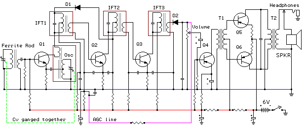
An AM receiver depends on the original carrier signal (station frequency) being amplitude modulated, meaning the original amplitude (strength) varies at an audio rate. Figure 1 illustrates an unmodulated carrier signal as it might appear on an oscilloscope, showing that...

fmradio
The FM radio project described here is based on the SONY 1619 chip. This is a single-chip radio, meaning that all functions from the antenna to the speaker are managed by the Sony integrated circuit, which is specifically designed for...
DIY FM Radio Kit
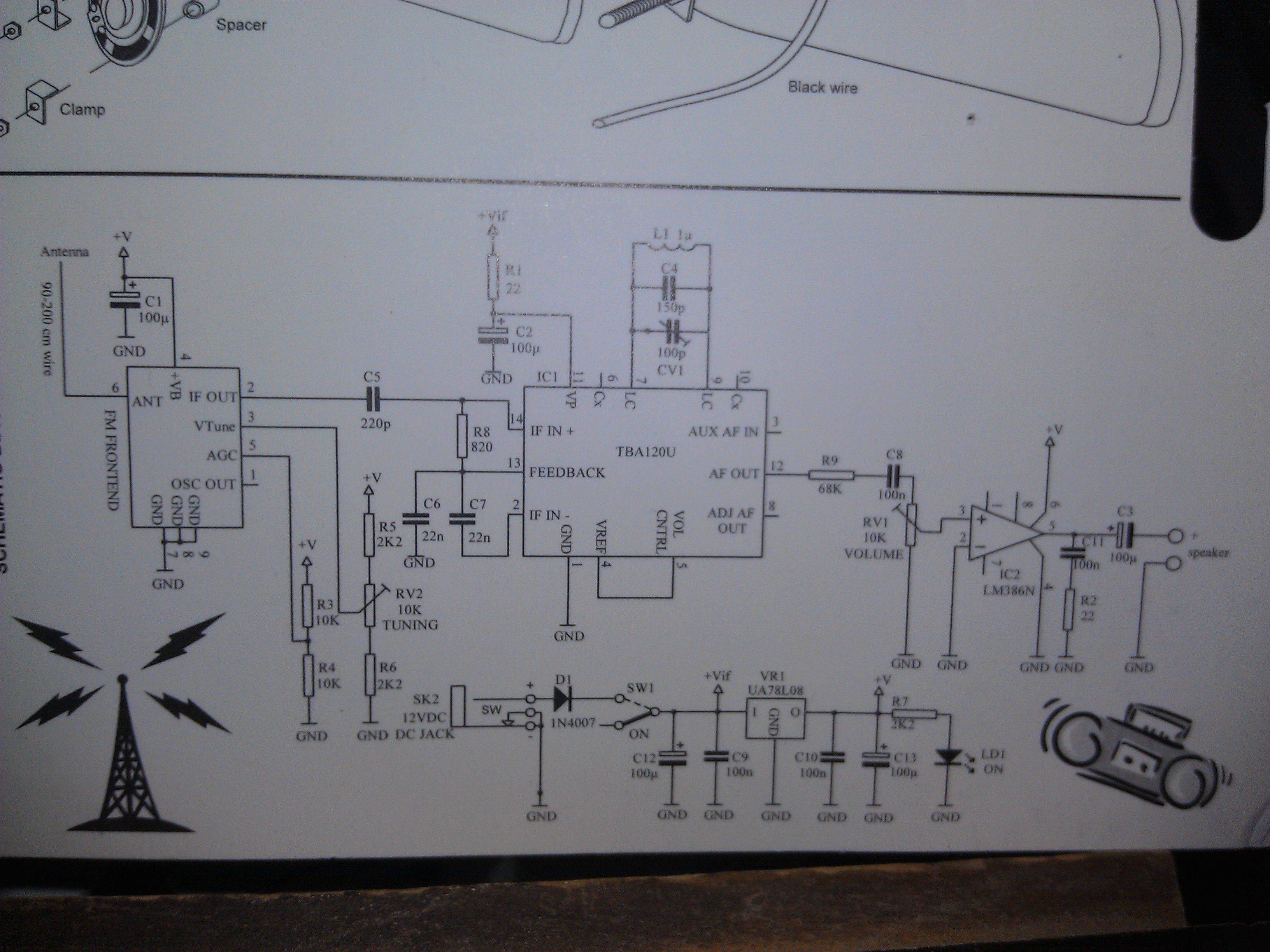
An FM Radio kit manufactured by Velleman-Kit and sold by Radioshack was recently assembled. The assembly process took approximately two hours, primarily due to distractions. The instructions provided are generally easy to follow, but they lack explicit details regarding the...

Sensitive FM Radio Tuner Circuit
This sensitive FM radio tuner is an ideal circuit for hobbyists who wish to construct their own tuners rather than purchasing a pre-assembled product.
The FM radio tuner circuit is designed to receive frequency modulation signals, providing a clear and stable...