


Simple sound trigger for cameras and flashes
#sound trigger
#photography
#high-speed photography
#camera
#flash
#sound sensor
#trigger circuit
#experimental

Description: This article describes how to build a simple yet effective sound trigger for cameras or flashes. The circuit allows for experimentation with high-speed photography.
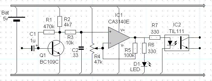
The sound trigger circuit is designed to activate a camera or flash unit in response to sound, making it particularly useful for capturing high-speed events such as balloon pops or other quick occurrences. The fundamental components of this circuit typically include a microphone, an amplifier, a comparator, and a relay or transistor to control the camera or flash.
The microphone serves as the initial sensor, detecting sound waves and converting them into an electrical signal. This signal is then amplified by an operational amplifier (op-amp) to ensure it is strong enough for further processing. The amplified signal is fed into a comparator, which is set to trigger when the sound level exceeds a predefined threshold. This threshold can be adjusted to suit various environments and sound levels.
Upon activation, the comparator output switches from low to high, which can be used to drive a transistor or relay. This component acts as a switch that closes the circuit to the camera or flash, initiating the capture of an image. The relay is particularly useful for isolating the camera's circuitry from the sound trigger circuit, protecting sensitive components from potential damage.
Additional features may include adjustable sensitivity controls, delay timers, or LED indicators to provide visual feedback when the trigger is activated. Power supply options for the circuit can vary, with battery-operated designs being common for portability, while wall adapters may be used for stationary setups.
This sound trigger circuit not only enhances the photography experience but also opens up opportunities for creative experimentation in capturing fleeting moments that would otherwise be difficult to document.This acticle describes how to build a simple yet effective sound trigger for cameras or flashes. The circuit allows to experiment with high-speed photography..
The sound trigger circuit is designed to activate a camera or flash unit in response to sound, making it particularly useful for capturing high-speed events such as balloon pops or other quick occurrences. The fundamental components of this circuit typically include a microphone, an amplifier, a comparator, and a relay or transistor to control the camera or flash.
The microphone serves as the initial sensor, detecting sound waves and converting them into an electrical signal. This signal is then amplified by an operational amplifier (op-amp) to ensure it is strong enough for further processing. The amplified signal is fed into a comparator, which is set to trigger when the sound level exceeds a predefined threshold. This threshold can be adjusted to suit various environments and sound levels.
Upon activation, the comparator output switches from low to high, which can be used to drive a transistor or relay. This component acts as a switch that closes the circuit to the camera or flash, initiating the capture of an image. The relay is particularly useful for isolating the camera's circuitry from the sound trigger circuit, protecting sensitive components from potential damage.
Additional features may include adjustable sensitivity controls, delay timers, or LED indicators to provide visual feedback when the trigger is activated. Power supply options for the circuit can vary, with battery-operated designs being common for portability, while wall adapters may be used for stationary setups.
This sound trigger circuit not only enhances the photography experience but also opens up opportunities for creative experimentation in capturing fleeting moments that would otherwise be difficult to document.This acticle describes how to build a simple yet effective sound trigger for cameras or flashes. The circuit allows to experiment with high-speed photography..

High-Speed Photos of Low-Speed Impacts
The objective is to capture various stages of a rapid process, especially in comparison to the resolution of the human eye. Due to the lack of advanced equipment such as a high-speed film camera, a practical setup utilizing a standard...

Sound light-flash trigger
Sound input to the microphone triggers the IC monostable circuit, which subsequently triggers an SCR, and hence the flash, after a time delay. This delay is adjustable by varying the monostable on-time from 5 milliseconds to 200 milliseconds.
The circuit described...

Sound trigger for flash unit
The circuit utilizes an operational amplifier (IC1) configured in a non-inverting amplifier mode. Resistors R1 and R2 establish a gain of approximately 500. The variable resistor RV1 (sensitivity) adjusts the bias of the non-inverting input to the negative supply voltage....

Basic Circuit Modification of Kodak Disposable Camera
The circuit diagram illustrates the original Kodak MAX Flash Unit, including the semiconductors that comprise the circuit. This diagram represents the unmodified version intended for the standard Kodak model, which should closely resemble the Kodak MAX model, if not identical....

Flash slave driver
In photography, a separate flash, triggered by the light of a master flash, is often required to provide additional light and fill in shadows. The sensitivity of this circuit depends on the proximity of the master flash and the value...

Catching the Falling Drop
The objective is to capture images of a rapid process, which occurs too quickly for the human eye to perceive, at precisely specified intervals with sub-millisecond accuracy. While utilizing specialized equipment like a high-speed camera would simplify this task, the...

sound origin direction finder
A sound origin direction indicator features a flat square shape with four sound transducer/amplifier units positioned at each corner. It includes four rows of solid-state lamps extending from the center to the corners and an electronic system integrated with the...
circuit trigger camera phone pda mp3
In night photography, long exposures are common, sometimes lasting several seconds to several minutes. HDR techniques often require taking a series of nine or more photos. Holding a remote trigger for an extended period can be tedious, leading to the...

Camera Head (A2075) Manual
The Camera Head (A2075) is a LWDAQ device designed to control and read a single ICX424 image sensor. The circuit includes a socket for soldering a 16-pin sensor directly and features a 12-way flex socket for connecting an auxiliary board...