


1972 Ford V8 alternator wiring diagram and voltage regulator
#alternator
#voltage regulator
#wiring diagram
#Ford V8
#polarity
#charging system
#1972 engine
#1968 Ford
#automotive electronics

Description: The vehicle is a 1968 Ford equipped with a 1972 engine. The original alternator has been replaced with a new unit. It has been suggested that reversing the polarity of the voltage regulator is necessary for the alternator to start functioning correctly. A wiring diagram for both the voltage regulator and the alternator is requested to assist with the installation.
To create a functional electrical system in this 1968 Ford with a 1972 engine, it is essential to understand the interaction between the alternator and the voltage regulator. The alternator generates electrical power, which is then regulated by the voltage regulator to ensure a consistent voltage output to the vehicle's electrical system and battery.
In this scenario, the new alternator may be designed for a different polarity than the original setup. Typically, older systems, such as those in a 1968 Ford, operate on positive ground, while many modern alternators are negative ground. To accommodate this, the voltage regulator's polarity must be reversed. This adjustment allows the alternator to charge the battery effectively.
The wiring connections for the alternator typically include:
1. **B+ Terminal**: This terminal connects to the battery positive terminal, providing the alternator with the necessary voltage to charge the battery.
2. **Field Terminal (F)**: This terminal connects to the voltage regulator, controlling the alternator's output based on the battery's charge level.
3. **Ground Terminal (G)**: This terminal must be connected to the vehicle's chassis ground to complete the circuit.
For the voltage regulator, the connections are as follows:
1. **Battery Terminal (B)**: This terminal connects to the positive side of the battery to receive voltage input from the alternator.
2. **Field Terminal (F)**: This terminal connects to the alternator's field terminal, allowing the regulator to control the alternator's output.
3. **Ground Terminal (G)**: This terminal is connected to the vehicle's ground to ensure proper operation of the regulator.
A detailed wiring diagram should illustrate these connections clearly, showing the alternator's B+ terminal connecting to the battery, the field terminal connecting to the voltage regulator, and the ground connections to the chassis. It is also important to ensure that the voltage regulator is correctly oriented to reflect the reversed polarity, allowing for proper voltage regulation and safe operation of the new alternator.
In conclusion, careful attention to the wiring and polarity adjustments is crucial for the successful integration of the new alternator into the 1968 Ford with a 1972 engine. The provided wiring diagram will serve as a valuable resource for ensuring all connections are made correctly, facilitating reliable vehicle operation.I have 1968 Ford and the motor identification is now a 1972 engine. Alternator was gone and I have a new one. Was told that I need to reverse the polarity of voltage regulator to make alternator start charging. A diagram of wiring to both voltage regulator and alternator would help.
To create a functional electrical system in this 1968 Ford with a 1972 engine, it is essential to understand the interaction between the alternator and the voltage regulator. The alternator generates electrical power, which is then regulated by the voltage regulator to ensure a consistent voltage output to the vehicle's electrical system and battery.
In this scenario, the new alternator may be designed for a different polarity than the original setup. Typically, older systems, such as those in a 1968 Ford, operate on positive ground, while many modern alternators are negative ground. To accommodate this, the voltage regulator's polarity must be reversed. This adjustment allows the alternator to charge the battery effectively.
The wiring connections for the alternator typically include:
1. **B+ Terminal**: This terminal connects to the battery positive terminal, providing the alternator with the necessary voltage to charge the battery.
2. **Field Terminal (F)**: This terminal connects to the voltage regulator, controlling the alternator's output based on the battery's charge level.
3. **Ground Terminal (G)**: This terminal must be connected to the vehicle's chassis ground to complete the circuit.
For the voltage regulator, the connections are as follows:
1. **Battery Terminal (B)**: This terminal connects to the positive side of the battery to receive voltage input from the alternator.
2. **Field Terminal (F)**: This terminal connects to the alternator's field terminal, allowing the regulator to control the alternator's output.
3. **Ground Terminal (G)**: This terminal is connected to the vehicle's ground to ensure proper operation of the regulator.
A detailed wiring diagram should illustrate these connections clearly, showing the alternator's B+ terminal connecting to the battery, the field terminal connecting to the voltage regulator, and the ground connections to the chassis. It is also important to ensure that the voltage regulator is correctly oriented to reflect the reversed polarity, allowing for proper voltage regulation and safe operation of the new alternator.
In conclusion, careful attention to the wiring and polarity adjustments is crucial for the successful integration of the new alternator into the 1968 Ford with a 1972 engine. The provided wiring diagram will serve as a valuable resource for ensuring all connections are made correctly, facilitating reliable vehicle operation.I have 1968 Ford and the motor identification is now a 1972 engine. Alternator was gone and I have a new one. Was told that I need to reverse the polarity of voltage regulator to make alternator start charging. A diagram of wiring to both voltage regulator and alternator would help.

DC Power Supply 9 volt using TIP31 transistor
This is a DC power supply circuit designed to regulate 9 volts and provide a current output ranging from 1 amp to 2 amps. The circuit utilizes a modified TIP31 transistor, although alternative transistors such as TIP41, MJE3055, or 2SC1061...
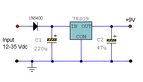
9 Volt 2 Amp Power Supply
This circuit primarily relies on the regulator for its functionality. The 78S09 regulator can provide a continuous output of up to 2 amps while ensuring a low noise and well-regulated supply. Although the circuit can operate without additional components, a...

Adjustable 3 Ampere Regulator
By combining a standard 78L05 voltage regulator with an integrated audio amplifier, specifically the TDA2030, it is possible to construct a simple yet effective adjustable voltage regulator. This regulator can output a voltage adjustable up to 20 V and handle...

Easy exchange of magnetic saturation voltage regulator circuit
Easy exchange of magnetic saturation voltage regulator circuit
The magnetic saturation voltage regulator circuit is designed to stabilize output voltage levels by utilizing magnetic saturation principles. This circuit typically employs a magnetic core, which operates in saturation to regulate voltage,...

12v power supply circuit
This project involves a straightforward and practical 12V power supply circuit utilizing the LM7812 integrated circuit (IC). The LM7812 is a three-terminal fixed voltage regulator IC housed in a TO-220 package. It incorporates several built-in features such as thermal shutdown,...

0-15 Volt 0-1A Power supply
TR1 provides a constant current to a bank of three zener diodes, thus maintaining a constant voltage independent of supply voltage variations. The resistor Rx is used to sense the PSU output current and to switch off the current to...

12 Volt 30 Amp PSU
Using a single 7812 IC voltage regulator and multiple outboard pass transistors, this power supply can deliver output load currents of up to 30 amps. The input transformer is likely to be the most expensive part of the entire project....
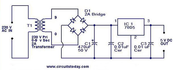
5V power supply using 7805 IC with circuit diagram
A 5V power supply using IC 7805 is designed and explained with a neat circuit diagram.
The circuit for a 5V power supply utilizing the IC 7805 voltage regulator is a straightforward and efficient design that provides a stable output voltage...

0-50V 1A power supply with CA3086
This power supply circuit is highly stabilized that its output voltage will drop only 0.005% even though the load changes from 0 to 100%. Another excellent capability is that the output voltage will change only by 0.01% if the input...