


automatic windshield washer
#windshield wiper
#sensor
#automotive electronics
#comfort functions
#automatic control
#car electronics
#rain sensor
#vehicle automation
#driver assistance
#comfort systems
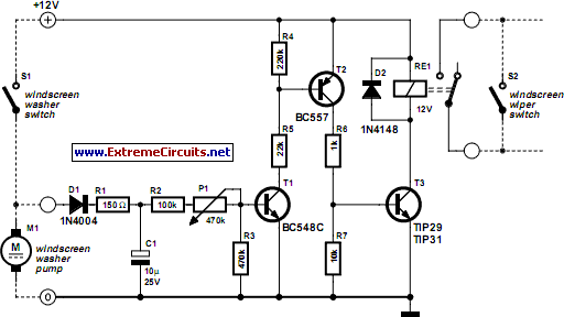
Description: Most recent cars are equipped with a significant amount of electronics, including ABS brake systems, engine control with injection calculators, airbag activation, and various comfort functions. One such function, which is often overlooked, is the automatic activation of windshield wipers for a few seconds after the windshield washer is used. This feature is essential as it prevents excess rinse product from dripping onto a freshly cleaned windshield. However, many lower-end or older vehicles lack this automatic function, which is a convenient addition. The circuit discussed here is simple and can be constructed with basic components that an electronics hobbyist typically has. This project keeps the windshield wiper activated for a few seconds after the windshield washer control is released. When the windshield washer pump operates, the 12 volts from the battery charge capacitor C1. After the washer stops, the capacitor discharges through R2, P1, R3, and the emitter-base junction of transistor T1, aided by diode D1. This keeps T1 conductive for a duration determined by the setting of P1. T1 saturates T2, which in turn saturates T3, activating relay Re1 that powers the windshield wiper by connecting it in parallel to the control switch. Once C1 is sufficiently discharged, T1 stops conducting, which subsequently deactivates T2 and T3, turning off relay Re1. The specific components are not critical; however, T3 should be a low-power NPN transistor with a gain over 25. Relay Re1 must be an automotive relay, capable of handling approximately 20 amps under 12 volts, available at car accessory shops or component retailers. The primary challenge in this project is to correctly identify the control wire for the windshield pump and the windshield wiper motor. A simple voltmeter can aid in this identification process.
The proposed circuit provides a practical solution for enhancing the functionality of older or lower-end vehicles lacking automatic windshield wiper activation. The circuit's operation relies on a few key components: a capacitor, resistors, transistors, and a relay. The capacitor (C1) is crucial as it stores energy when the windshield washer is activated, ensuring that the wipers continue to operate for a set duration afterward. The resistors (R2, R3) and potentiometer (P1) are used to control the discharge rate of the capacitor, allowing for adjustable timing of the wiper operation.
Transistors T1, T2, and T3 serve as amplifiers and switches within the circuit. T1 is responsible for maintaining the conductive state while the capacitor discharges, thereby controlling the subsequent transistors. T2 and T3 work in tandem to activate the relay (Re1), which connects the windshield wiper motor to the power supply, enabling the wipers to continue functioning after the washer is turned off.
The relay (Re1) is an essential component, as it must be rated for automotive use to handle the current drawn by the windshield wiper motor. Its ability to maintain contact under load is critical for reliable operation. The identification of the correct control wires is paramount to the success of the installation. Proper testing with a voltmeter is recommended to ensure that connections are made accurately, preventing potential damage to the vehicle's electrical system.
Overall, this circuit is a straightforward project that enhances vehicle convenience and functionality, making it an excellent addition for automotive enthusiasts and hobbyists.Most, if not all, recent cars have an impressive amount of electronics, whether it be ABS brake systems, engine control with injection calculators, airbag activation, or other various functions, called comfort functions. Among them is one which we tend to forget because it has become so common today. It turns on the windshield wipers automatically for a few seconds after the windshield cleaner. This practice is almost indispensable because it avoids any dripping of excess rinse product right in the middle of a just-cleaned windshield. Unfortunately, many low end` cars or some of the older cars are not equipped with this automatic function which is a very nice convenience to have.
So, since all that is required is a handful of components that any electronics hobbyist worthy of the name already has in his/her drawer, we will discuss the circuit proposed here. This project is super simple and simply keeps the windshield wiper activated for a few seconds after the windshield washer control contact has been released.
While the windshield washer pump is operating, the 12 volts delivered by the battery are present at the terminals and are therefore charging capacitor C1. Once the windshield washer has stopped, this capacitor can only discharge through R2, P1, R3, and the T1 emitter-base junction, due to the presence of diode D1.
It thus keeps T1 in the conductive state during a certain time, the exact period of which depends on the setting of P1. T1 in turn saturates T2, which then does the same for T3. The Re1 relay is therefore connected which maintains the windshield wiper in operation because its work contact is wired in parallel to the control switch.
Once C1 is sufficiently discharged, T1 is blocked, which then blocks T2 and T3 and deactivates relay Re1. The type of components is not really critical, even if we indicate specific reference numbers for T3, any low-power npn transistor with a gain over 25 will work.
However, considering the amount of power consumed by the windshield wiper motor, relay Re1 will imperatively be an automobile` relay. You can find very low-priced ones at many car accessory shops (and even at some component retailers).
These relays maintain contact under 12 volts and often do not have more than one work contact but they are, in general, capable of cutting off about 20 amps. Finally, the only delicate point of this project is to properly identify the control wire for the windshield pump on one hand, and the windshield wiper motor on the other.
Observing what is happening at the various connections with a simple voltmeter, should get it right without too much difficulty.
The proposed circuit provides a practical solution for enhancing the functionality of older or lower-end vehicles lacking automatic windshield wiper activation. The circuit's operation relies on a few key components: a capacitor, resistors, transistors, and a relay. The capacitor (C1) is crucial as it stores energy when the windshield washer is activated, ensuring that the wipers continue to operate for a set duration afterward. The resistors (R2, R3) and potentiometer (P1) are used to control the discharge rate of the capacitor, allowing for adjustable timing of the wiper operation.
Transistors T1, T2, and T3 serve as amplifiers and switches within the circuit. T1 is responsible for maintaining the conductive state while the capacitor discharges, thereby controlling the subsequent transistors. T2 and T3 work in tandem to activate the relay (Re1), which connects the windshield wiper motor to the power supply, enabling the wipers to continue functioning after the washer is turned off.
The relay (Re1) is an essential component, as it must be rated for automotive use to handle the current drawn by the windshield wiper motor. Its ability to maintain contact under load is critical for reliable operation. The identification of the correct control wires is paramount to the success of the installation. Proper testing with a voltmeter is recommended to ensure that connections are made accurately, preventing potential damage to the vehicle's electrical system.
Overall, this circuit is a straightforward project that enhances vehicle convenience and functionality, making it an excellent addition for automotive enthusiasts and hobbyists.Most, if not all, recent cars have an impressive amount of electronics, whether it be ABS brake systems, engine control with injection calculators, airbag activation, or other various functions, called comfort functions. Among them is one which we tend to forget because it has become so common today. It turns on the windshield wipers automatically for a few seconds after the windshield cleaner. This practice is almost indispensable because it avoids any dripping of excess rinse product right in the middle of a just-cleaned windshield. Unfortunately, many low end` cars or some of the older cars are not equipped with this automatic function which is a very nice convenience to have.
So, since all that is required is a handful of components that any electronics hobbyist worthy of the name already has in his/her drawer, we will discuss the circuit proposed here. This project is super simple and simply keeps the windshield wiper activated for a few seconds after the windshield washer control contact has been released.
While the windshield washer pump is operating, the 12 volts delivered by the battery are present at the terminals and are therefore charging capacitor C1. Once the windshield washer has stopped, this capacitor can only discharge through R2, P1, R3, and the T1 emitter-base junction, due to the presence of diode D1.
It thus keeps T1 in the conductive state during a certain time, the exact period of which depends on the setting of P1. T1 in turn saturates T2, which then does the same for T3. The Re1 relay is therefore connected which maintains the windshield wiper in operation because its work contact is wired in parallel to the control switch.
Once C1 is sufficiently discharged, T1 is blocked, which then blocks T2 and T3 and deactivates relay Re1. The type of components is not really critical, even if we indicate specific reference numbers for T3, any low-power npn transistor with a gain over 25 will work.
However, considering the amount of power consumed by the windshield wiper motor, relay Re1 will imperatively be an automobile` relay. You can find very low-priced ones at many car accessory shops (and even at some component retailers).
These relays maintain contact under 12 volts and often do not have more than one work contact but they are, in general, capable of cutting off about 20 amps. Finally, the only delicate point of this project is to properly identify the control wire for the windshield pump on one hand, and the windshield wiper motor on the other.
Observing what is happening at the various connections with a simple voltmeter, should get it right without too much difficulty.

Add a sensor to a board and measure something with it
This week's plan is to build a device that warns of the potential for a knockdown, which is the process by which an over-canvassed ship is laid over on her beam-ends. The risk of sinking is high during this event,...

Windshield wiper controller
This circuit provides complete speed control over a car's windshield wipers. The wipers can be slowed down to any rate, even down to four sweeps per minute. The controller consists of two principal circuits: the rate-determining circuit, which is a...

Pots water alarm circuit
The flowers in pots require watering, as relying solely on the observation of moist soil surfaces can be unreliable. To address this issue, a flower watering indicator has been developed. This circuit includes a field effect transistor (VT1), a second...

Wire Break Sensor Alarm Circuit Schematic
The circuit of a loop sensor-based simple security alarm is described here. The sensor loop consists of a short length of thin enamelled copper wire.
The loop sensor security alarm operates on the principle of detecting interruptions in the circuit formed...
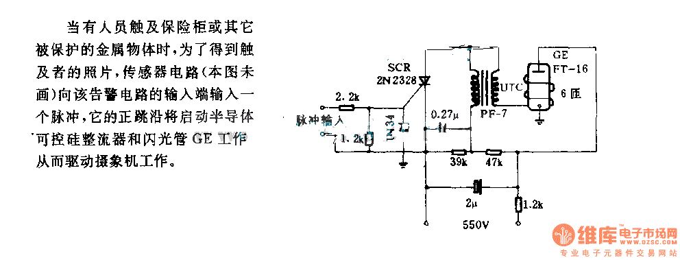
The alarm circuit diagram for safety box and other metal objects
When an individual touches the safety box or other protected metal objects, the sensor circuit generates a pulse to the alarm circuit. The positive edge of this pulse activates the semiconductor and thyristor flash GE, subsequently triggering the camera to...

Drinking fountains automatic control circuit diagram
The circuit diagram for the automatic control of drinking fountains is presented below.
The automatic control circuit for drinking fountains typically employs a combination of sensors and control elements to manage the operation of the fountain efficiently. The main components of...

Automatic light regulator circuit diagram
This circuit is designed to automatically adjust the brightness of lights based on the ambient light intensity. In bright conditions, the lights remain off, while in low ambient brightness, the lights are activated. The circuit incorporates a thyristor (VT1) and...
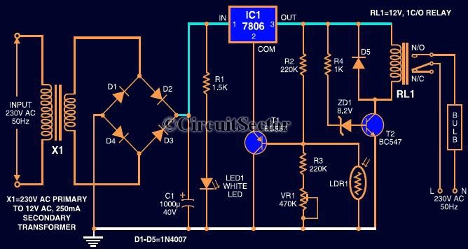
Automatic Light Controller Using 7806 And LDR PCB
This circuit automates the control of street or porch lights. The automatic lamp controller circuit utilizes a 7806 voltage regulator IC, which can be employed to automate street lights, tube lights, or any other home electrical lighting systems. The IC...
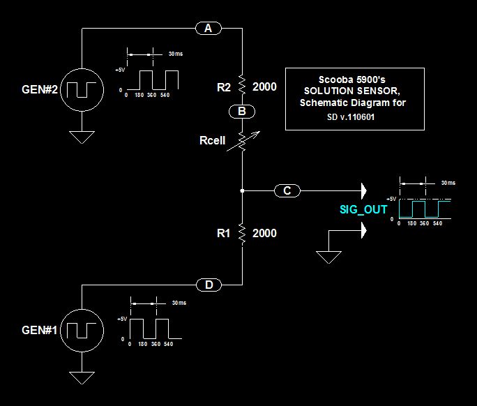
Scoobas Solution Sensing Tactic
This document serves multiple purposes, primarily to document the methods employed by a Scooba robot to detect: a) the presence of an acceptable cleaning solution being delivered to its pump, and b) the excess presence of used solution collected off...