


Windshield wiper controller
#windshield wiper
#speed control
#car
#automotive
#controller
#motor control
#variable speed
#wiper system

Description: This circuit provides complete speed control over a car's windshield wipers. The wipers can be slowed down to any rate, even down to four sweeps per minute. The controller consists of two principal circuits: the rate-determining circuit, which is a unijunction transistor configured as a free-running oscillator, and the silicon-controlled rectifier, which serves as the actuator.
The windshield wiper speed control circuit is designed to offer variable speed adjustments, enhancing the driver's ability to manage wiper operation under different weather conditions. The core of the circuit is the unijunction transistor (UJT), which operates as a free-running oscillator. This oscillator generates a pulse-width modulation (PWM) signal that dictates the timing of the wiper motor's operation.
The UJT is characterized by its ability to produce a continuous oscillation, where the frequency of the oscillation can be adjusted by varying the resistance in the timing circuit. This resistance, typically implemented using a potentiometer, allows for fine-tuning of the wiper speed. The output from the UJT is fed into the gate of a silicon-controlled rectifier (SCR), which functions as the actuator in this system. The SCR is a semiconductor device that can control the power delivered to the wiper motor by varying the phase angle of the AC supply voltage.
As the PWM signal from the UJT varies, it triggers the SCR to conduct for different durations, effectively controlling the average power supplied to the wiper motor. This results in a smooth transition between different speeds, allowing the wipers to operate at a minimum of four sweeps per minute up to their maximum speed. The design is robust and reliable, ensuring that the windshield wipers can be adjusted according to the driver's preference and environmental conditions, thereby improving visibility and safety while driving.This circuit provides complete speed control over car"s windshield wipers. They can be slowed down to any rate even down to four sweeps per minute The controller has two principal circuits: The rate-determining circuit—a unijunction transistor connected as a freerunning oscillator, and the silicon-controlled rectifier which is the actuator.
The windshield wiper speed control circuit is designed to offer variable speed adjustments, enhancing the driver's ability to manage wiper operation under different weather conditions. The core of the circuit is the unijunction transistor (UJT), which operates as a free-running oscillator. This oscillator generates a pulse-width modulation (PWM) signal that dictates the timing of the wiper motor's operation.
The UJT is characterized by its ability to produce a continuous oscillation, where the frequency of the oscillation can be adjusted by varying the resistance in the timing circuit. This resistance, typically implemented using a potentiometer, allows for fine-tuning of the wiper speed. The output from the UJT is fed into the gate of a silicon-controlled rectifier (SCR), which functions as the actuator in this system. The SCR is a semiconductor device that can control the power delivered to the wiper motor by varying the phase angle of the AC supply voltage.
As the PWM signal from the UJT varies, it triggers the SCR to conduct for different durations, effectively controlling the average power supplied to the wiper motor. This results in a smooth transition between different speeds, allowing the wipers to operate at a minimum of four sweeps per minute up to their maximum speed. The design is robust and reliable, ensuring that the windshield wipers can be adjusted according to the driver's preference and environmental conditions, thereby improving visibility and safety while driving.This circuit provides complete speed control over car"s windshield wipers. They can be slowed down to any rate even down to four sweeps per minute The controller has two principal circuits: The rate-determining circuit—a unijunction transistor connected as a freerunning oscillator, and the silicon-controlled rectifier which is the actuator.
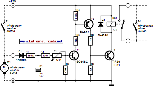
automatic windshield washer
Most recent cars are equipped with a significant amount of electronics, including ABS brake systems, engine control with injection calculators, airbag activation, and various comfort functions. One such function, which is often overlooked, is the automatic activation of windshield wipers...

Quadruple semi-continuous casting machine speed control circuit
The circuit encompasses a main circuit, a trigger circuit, speed negative feedback, negative feedback differential voltage, a current cut-off circuit, loss of field protection, and other components. Given that the motor power is small (1.1 kW), a single-phase circuit is...

Car battery charger Automative car and motorcycle schematics
The circuit is designed to operate with an external power supply, which is why it does not include a transformer, rectifier, or filter capacitors in the schematic. However, these components can be added if desired. To utilize the circuit, connect...

Motor control circuit for forward and reverse phase induction
This is the power diagram for motor forward and reverse operation. To change the motor direction, one polarity must be altered, for example, changing R to S. For detailed information, please refer to the following.
The described power diagram illustrates a...

Direction and speed control
This circuit functions similarly to the one depicted in Fig. 57-4. The key differences include the placement of the field across the rectified supply and the armature being positioned within the SCR bridge. Therefore, the field current is unidirectional while...

Motorized Video Camera Mount
The camera rotator circuit utilizes a 2716 EPROM to store a logic value table that governs the motor driver (H-bridge) circuit. The schematic illustrates the EPROM data. By employing the EPROM, a significant number of discrete gates are eliminated. The...

Car brake Light
What's so special about this circuit? Well, the first third-brake light I installed I had to pull a wire from the Third Brake Light all the way underneath the carpet to the brake-pedal-switch and I thought it would be easier...

motor timer
The primary concept is to rotate the motor slightly every 15 seconds. A monofilament line conveys the motion to the ornament, which is wound by the motor and gradually unwinds as the ornament turns. The charging circuit includes a 1...

controller
As summer approaches, many individuals focus on staying cool during hot days. For some, this means turning on the air conditioner and enjoying a cold beverage. However, it is essential to consider how to maintain the temperature of radio equipment...