


36V battery charger
#36V battery
#constant voltage
#44V
#1A max
#e-bike
#battery compartment
#permanent connection
#charging circuit
#power management

Description: A constant voltage battery charger is required, with an output of 44V and a maximum current of 1A. This charger will be integrated into the battery compartment of an e-bike and will maintain a permanent connection to the three 1...
The design of a constant voltage battery charger for an e-bike involves several critical components to ensure reliable performance and safety. The charger must be capable of delivering a steady output voltage of 44V while limiting the current to a maximum of 1A.
The primary components of the circuit include a transformer, rectifier, voltage regulator, and necessary protection circuits. The transformer steps down the input AC voltage to a suitable level before it is rectified. A full-wave bridge rectifier can be employed to convert the AC voltage into pulsating DC.
Following the rectification process, a smoothing capacitor is used to reduce the ripple voltage, providing a more stable DC output. The voltage regulator, possibly utilizing an integrated circuit such as the LM317 configured for constant voltage operation, will ensure that the output remains at 44V regardless of variations in input voltage or load conditions.
Incorporating a current limiting feature is essential to prevent overcharging the battery. This can be achieved by using a simple resistor in series with the output or by implementing a more sophisticated current sensing circuit that adjusts the output based on the battery's charging state.
Protection mechanisms such as thermal fuses or resettable fuses should be included to safeguard against overheating or short circuits. Additionally, it is advisable to include a status indicator (LED) to signal when the charger is active and functioning correctly.
The charger must be designed to fit within the confined space of the e-bike battery compartment, ensuring that all components are securely mounted and insulated to prevent any risk of short circuits or damage during operation. Proper heat dissipation measures should also be considered, as charging can generate heat, which may affect the performance and longevity of the components.
Overall, the design should comply with relevant safety standards and regulations to ensure that the charger operates safely and efficiently while being integrated into the e-bike's battery system.I need a constant voltage 44V, 1A max battery charger. This will be built into the battery compartment of an e-bike, and will be permanently connected to the three 1..
The design of a constant voltage battery charger for an e-bike involves several critical components to ensure reliable performance and safety. The charger must be capable of delivering a steady output voltage of 44V while limiting the current to a maximum of 1A.
The primary components of the circuit include a transformer, rectifier, voltage regulator, and necessary protection circuits. The transformer steps down the input AC voltage to a suitable level before it is rectified. A full-wave bridge rectifier can be employed to convert the AC voltage into pulsating DC.
Following the rectification process, a smoothing capacitor is used to reduce the ripple voltage, providing a more stable DC output. The voltage regulator, possibly utilizing an integrated circuit such as the LM317 configured for constant voltage operation, will ensure that the output remains at 44V regardless of variations in input voltage or load conditions.
Incorporating a current limiting feature is essential to prevent overcharging the battery. This can be achieved by using a simple resistor in series with the output or by implementing a more sophisticated current sensing circuit that adjusts the output based on the battery's charging state.
Protection mechanisms such as thermal fuses or resettable fuses should be included to safeguard against overheating or short circuits. Additionally, it is advisable to include a status indicator (LED) to signal when the charger is active and functioning correctly.
The charger must be designed to fit within the confined space of the e-bike battery compartment, ensuring that all components are securely mounted and insulated to prevent any risk of short circuits or damage during operation. Proper heat dissipation measures should also be considered, as charging can generate heat, which may affect the performance and longevity of the components.
Overall, the design should comply with relevant safety standards and regulations to ensure that the charger operates safely and efficiently while being integrated into the e-bike's battery system.I need a constant voltage 44V, 1A max battery charger. This will be built into the battery compartment of an e-bike, and will be permanently connected to the three 1..

One simple charging circuit b porcelain
After a slight loss of field strength, magnets can be re-magnetized using a simple homemade porcelain filler. Locate scrap materials such as switches and contacts, as well as other models like CJ10-60 ~ 15. The circuit can operate at 0A...

Control a processor`s power supply in real time
In battery-powered applications in which power management is key, a microprocessor may adjust its core voltage corresponding to an increase or a decrease in clock speed, allowing full processing power when necessary but not wasting excess power when idle. The...

CW117 CW217 CW317 12V constant-voltage charger
A 12V constant voltage charger is depicted. The power supply circuit shares the same basic design. The resistor R1, valued at 0.2 ohms, serves a limiting function, effectively increasing the internal resistance of the charger, which in turn reduces the...

Charging circuit from the DC power supply switching power supply control
Charging circuit from the DC power supply switching power supply control
The charging circuit described is designed to operate with a DC power supply, utilizing a switching power supply control mechanism. This type of circuit is commonly employed in applications where...
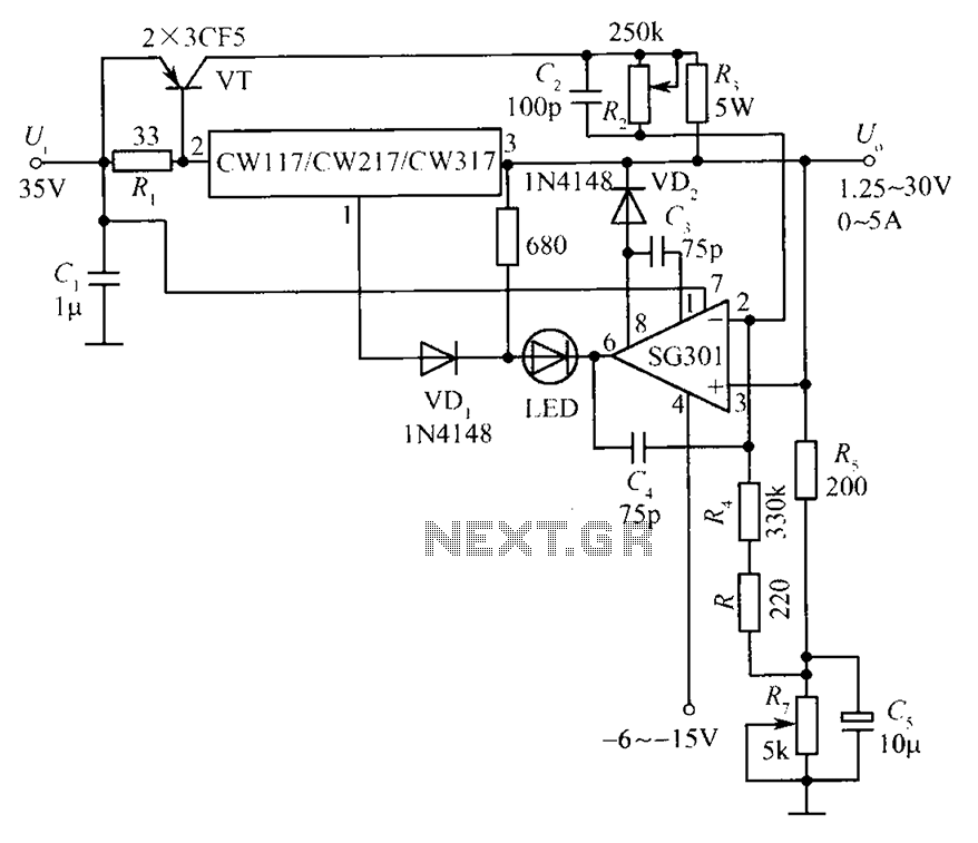
CW117 CW217 CW317 schematic configuration of the constant voltage constant current source
This document presents a diagram of a constant voltage/current power supply box. It is composed of three main components: spread current, constant voltage, and constant current. The design features two 3CF5 power transistors arranged in parallel, functioning as an extension...

Power Path Management Battery Charger
Powering the system is required by many applications while charging the battery simultaneously. Interaction between the system and charger may result in a...
Power management in electronic systems is critical, particularly in applications that necessitate simultaneous operation and battery charging. This...

contsant voltage current limited charger
Constant Voltage Current Limited Charger power supply. Refer to the page for an explanation regarding the associated circuit diagram.
The Constant Voltage Current Limited Charger power supply is designed to provide a stable output voltage while limiting the current to protect...

Constant Voltage measuring circuit
The circuit for bridge measurements is straightforward, as illustrated in the figure. The sensor bridge drive voltage can be adjusted between +4V and +10V, depending on the specific requirements of the sensor. Two fixed gain options of 333.3 and 500...
Power Path Management Battery Charger
Powering the system is required by many applications while charging the battery simultaneously. Interaction between the system and charger may result in a...
Power management in electronic systems is critical, particularly in applications that necessitate simultaneous operation and battery charging. This...