


LNK616PG 5 volt constant charger circuit design electronic project
#LNK616PG
#constant voltage
#constant current
#power supply
#cell phone charger
#LinkSwitch-II
#universal-input
#low cost
#adapter

Description: A very simple 5-volt constant voltage, constant current (CV/CC) universal-input power supply for cell phone or similar charger applications can be designed using the LNK616PG product from the LinkSwitch-II family. This low-cost charger adapter accepts a wide range of input voltage, from 85 VAC up to 265 VAC, and will provide a fixed 5-volt DC output at a maximum output current of 1 ampere. The LNK616PG features an integrated 700 V switching MOSFET and an ON/OFF control function, which together deliver high efficiency under all load conditions while minimizing no-load energy consumption. The AC input power is rectified by diodes D1 through D4. The rectified DC is filtered by the bulk storage capacitors C1 and C2. Inductors L1 and L2, along with capacitors C1 and C2, form pi filters to attenuate conducted differential-mode EMI noise. The rectified and filtered input voltage is applied to one end of the transformer (T1) primary winding. The other side of the transformer’s primary winding is driven by the internal MOSFET of U1. An RCD-R clamp, consisting of D5, R3, R4, and C3, limits drain voltage spikes caused by leakage inductance.
The power supply circuit described employs the LNK616PG from the LinkSwitch-II series, which is specifically designed for applications requiring a compact and efficient power solution. The device operates within a wide input voltage range, making it suitable for global use. The internal switching MOSFET allows for efficient energy conversion, while the ON/OFF control helps in reducing power consumption when the load is not present.
The rectification process is accomplished using a bridge rectifier configuration with diodes D1 through D4, converting the AC input to a pulsating DC voltage. The bulk storage capacitors C1 and C2 smooth out the pulsating DC, providing a stable voltage level for further processing. The use of pi filters created by inductors L1 and L2 in conjunction with capacitors C1 and C2 is essential for minimizing electromagnetic interference (EMI) that could affect other devices in proximity. This filtering ensures compliance with EMI regulations while maintaining signal integrity.
The transformer T1 plays a crucial role in isolating the output from the input, providing both voltage transformation and safety isolation. The control circuitry, which includes the internal MOSFET of U1, regulates the output voltage and current to ensure that the specified 5V at 1A is consistently delivered to the load.
To protect the circuit from voltage spikes that may occur due to leakage inductance, an RCD-R clamp is implemented. This clamp comprises diodes D5, resistors R3 and R4, and capacitor C3, effectively shunting excess energy away from the MOSFET and preventing damage from high-voltage transients.
Overall, this design illustrates a robust and efficient solution for powering devices such as cell phones, ensuring reliability and adherence to electrical standards.A very simple 5 volt constant voltage, constant current (CV/CC) universal-input power supply for cell phone or similar charger applications can be designed using the LNK616PG product from the LinkSwitch-II family. As you can see in the circuit diagram, this low cost charger, adapter accepts a wide range of input voltage, from 85 VAC up to 265 VA
C and will provide a fixed 5 volt DC output at a maximum output current of 1 ampere. The LNK616PG has an integrated 700 V switching MOSFET and ON/OFF control function which together deliver high efficiency under all load conditions and low no-load energy consumption. The AC input power is rectified by diodes D1 through D4. The rectified DC is filtered by the bulk storage capacitors C1 and C2. Inductors L1 and L2, with capacitors C1 and C2, form pi filters to attenuate conducted differential-mode EMI noise.
The rectified and filtered input voltage is applied to one end of the transformer (T1) primary winding. The other side of the transformer`s primary winding is driven by the internal MOSFET of U1. An RCD-R clamp consisting of D5, R3, R4, and C3 limits drain voltage spikes caused by leakage inductance.
The power supply circuit described employs the LNK616PG from the LinkSwitch-II series, which is specifically designed for applications requiring a compact and efficient power solution. The device operates within a wide input voltage range, making it suitable for global use. The internal switching MOSFET allows for efficient energy conversion, while the ON/OFF control helps in reducing power consumption when the load is not present.
The rectification process is accomplished using a bridge rectifier configuration with diodes D1 through D4, converting the AC input to a pulsating DC voltage. The bulk storage capacitors C1 and C2 smooth out the pulsating DC, providing a stable voltage level for further processing. The use of pi filters created by inductors L1 and L2 in conjunction with capacitors C1 and C2 is essential for minimizing electromagnetic interference (EMI) that could affect other devices in proximity. This filtering ensures compliance with EMI regulations while maintaining signal integrity.
The transformer T1 plays a crucial role in isolating the output from the input, providing both voltage transformation and safety isolation. The control circuitry, which includes the internal MOSFET of U1, regulates the output voltage and current to ensure that the specified 5V at 1A is consistently delivered to the load.
To protect the circuit from voltage spikes that may occur due to leakage inductance, an RCD-R clamp is implemented. This clamp comprises diodes D5, resistors R3 and R4, and capacitor C3, effectively shunting excess energy away from the MOSFET and preventing damage from high-voltage transients.
Overall, this design illustrates a robust and efficient solution for powering devices such as cell phones, ensuring reliability and adherence to electrical standards.A very simple 5 volt constant voltage, constant current (CV/CC) universal-input power supply for cell phone or similar charger applications can be designed using the LNK616PG product from the LinkSwitch-II family. As you can see in the circuit diagram, this low cost charger, adapter accepts a wide range of input voltage, from 85 VAC up to 265 VA
C and will provide a fixed 5 volt DC output at a maximum output current of 1 ampere. The LNK616PG has an integrated 700 V switching MOSFET and ON/OFF control function which together deliver high efficiency under all load conditions and low no-load energy consumption. The AC input power is rectified by diodes D1 through D4. The rectified DC is filtered by the bulk storage capacitors C1 and C2. Inductors L1 and L2, with capacitors C1 and C2, form pi filters to attenuate conducted differential-mode EMI noise.
The rectified and filtered input voltage is applied to one end of the transformer (T1) primary winding. The other side of the transformer`s primary winding is driven by the internal MOSFET of U1. An RCD-R clamp consisting of D5, R3, R4, and C3 limits drain voltage spikes caused by leakage inductance.

Adjustable Constant Current Regulator
This is an adjustable constant current regulator circuit. This circuit can be used in a bench power supply to prevent the circuits that are tested from being damaged.
The adjustable constant current regulator circuit is designed to provide a stable output...

Switching power supply drive circuit
Driver circuit diagram: The primary function of the driver circuit is to serve as a variable width pulse width modulator output power amplifier, providing a drive signal to high voltage power switching devices. The driving circuit typically plays a role...

Changhong DVB-2000 digital satellite receiver switching power supply circuit
The Changhong DVB-2000 digital satellite receiver features a switching power supply circuit. This circuit primarily comprises a power input section, an oscillation switching circuit, and a DC output section. The power input circuit receives 22V AC from a step-down transformer,...

Designing Multiple Output Power Supplies With Topswitch
This application note describes a digital blood pressure meter concept that utilizes integrated pressure sensor analog signal-conditioning circuitry, microcontroller hardware/software, and a liquid crystal display. The sensing system measures cuff pressure (CP) and extracts pulses for analysis to determine systolic...

0-12V 2A power supply
This project has two options. It can be a mains operated project, using a 2155 or 2156 transformer or it can be connected to a plug pack. We recommend it be connected to a 16v AC 1 amp plug pack...

CW117 CW217 CW317 12V constant-voltage charger
A 12V constant voltage charger is depicted. The power supply circuit shares the same basic design. The resistor R1, valued at 0.2 ohms, serves a limiting function, effectively increasing the internal resistance of the charger, which in turn reduces the...

Sony KV-S29MHl TV switching power supply (SIR a 80145A) circuit diagram
The circuit of the Sony KV-S29MHl (S Movement series) TV switching power supply (SIR a 80145A) consists of three main sections: (A) the power oscillation part, (B) the regulator part, and (C) the output section.
The Sony KV-S29MHl TV switching power...
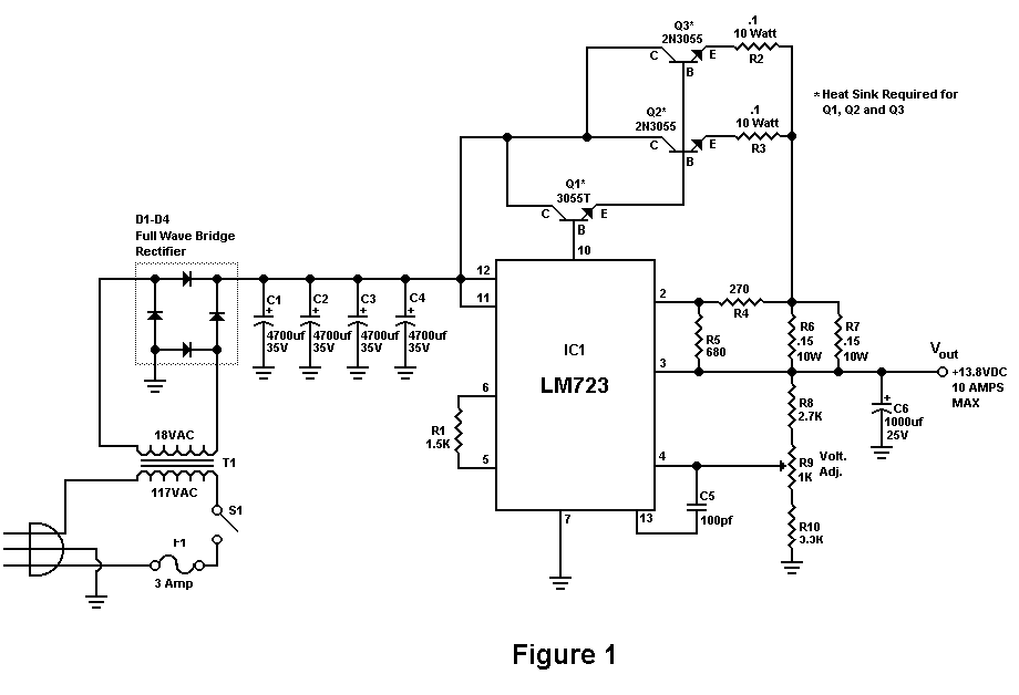
Build A 10 Amp 13.8 Volt Power Supply
Sometimes amateurs like to home-brew their power supplies instead of purchasing one off the shelf at any of the major ham radio retail dealers. The advantage to rolling your own power supply is that it teaches us how they work...

Low drift constant current source circuit by the MIC2951
The circuit illustrated in the figure utilizes the low-drift current source circuit MIC2951, which is designed to provide specific output current values.
The MIC2951 is a precision voltage regulator that can also be configured to function as a low-drift current source....