


nimh charger circuit diagram
#NiMH charger
#ADM66A
#battery charger
#lead acid battery
#lithium battery
#automatic charger
#12V charger
#circuit diagram
#simple charger

Description: NiMH charger circuit diagram using ADM66A. Related searches include charger circuit, NiMH charger circuit, lead acid battery charger circuit, LiPo charger circuit, automatic battery charger circuit, simple battery charger circuit, lithium battery charger circuit, charger circuit diagram, and 12V charger circuit.
The NiMH charger circuit employing the ADM66A is designed to efficiently charge nickel-metal hydride (NiMH) batteries. The ADM66A is a dedicated battery charger IC that offers features such as constant current charging and automatic cut-off when the battery reaches full charge, ensuring safety and longevity of the battery.
The circuit typically consists of an input power supply, which provides the necessary voltage and current to the ADM66A. The input voltage is often regulated to a specific level, ensuring that the IC operates within its optimal range. A rectifier may be included to convert AC voltage to DC if an AC source is used.
The ADM66A controls the charging process by regulating the output current supplied to the battery. It incorporates a feedback mechanism to monitor the battery voltage and adjust the charging current accordingly. This is crucial for preventing overcharging, which can lead to battery damage or reduced lifespan.
Additional components in the circuit may include resistors for current sensing, capacitors for stabilizing voltage, and diodes for protecting against reverse polarity. An LED indicator can also be integrated to signal the charging status, providing visual feedback to the user.
For enhanced functionality, the circuit can be designed with additional features such as temperature monitoring to prevent overheating, or a microcontroller interface for programmable charging profiles. This flexibility allows the charger to accommodate various battery chemistries and capacities, making it a versatile solution for battery management.
Overall, the NiMH charger circuit with the ADM66A provides a reliable and efficient means of charging NiMH batteries, suitable for a wide range of applications, from consumer electronics to electric vehicles.NiMH CHARGER Circuit diagram using ADM66A Searches related to CHARGER Circuit, nimh charger circuit, lead acid battery charger circuit, lipo charger circuit, automatic battery charger circuit, simple battery charger circuit, lithium battery charger circuit, charger circuit diagram, charger circuit 12v..
The NiMH charger circuit employing the ADM66A is designed to efficiently charge nickel-metal hydride (NiMH) batteries. The ADM66A is a dedicated battery charger IC that offers features such as constant current charging and automatic cut-off when the battery reaches full charge, ensuring safety and longevity of the battery.
The circuit typically consists of an input power supply, which provides the necessary voltage and current to the ADM66A. The input voltage is often regulated to a specific level, ensuring that the IC operates within its optimal range. A rectifier may be included to convert AC voltage to DC if an AC source is used.
The ADM66A controls the charging process by regulating the output current supplied to the battery. It incorporates a feedback mechanism to monitor the battery voltage and adjust the charging current accordingly. This is crucial for preventing overcharging, which can lead to battery damage or reduced lifespan.
Additional components in the circuit may include resistors for current sensing, capacitors for stabilizing voltage, and diodes for protecting against reverse polarity. An LED indicator can also be integrated to signal the charging status, providing visual feedback to the user.
For enhanced functionality, the circuit can be designed with additional features such as temperature monitoring to prevent overheating, or a microcontroller interface for programmable charging profiles. This flexibility allows the charger to accommodate various battery chemistries and capacities, making it a versatile solution for battery management.
Overall, the NiMH charger circuit with the ADM66A provides a reliable and efficient means of charging NiMH batteries, suitable for a wide range of applications, from consumer electronics to electric vehicles.NiMH CHARGER Circuit diagram using ADM66A Searches related to CHARGER Circuit, nimh charger circuit, lead acid battery charger circuit, lipo charger circuit, automatic battery charger circuit, simple battery charger circuit, lithium battery charger circuit, charger circuit diagram, charger circuit 12v..
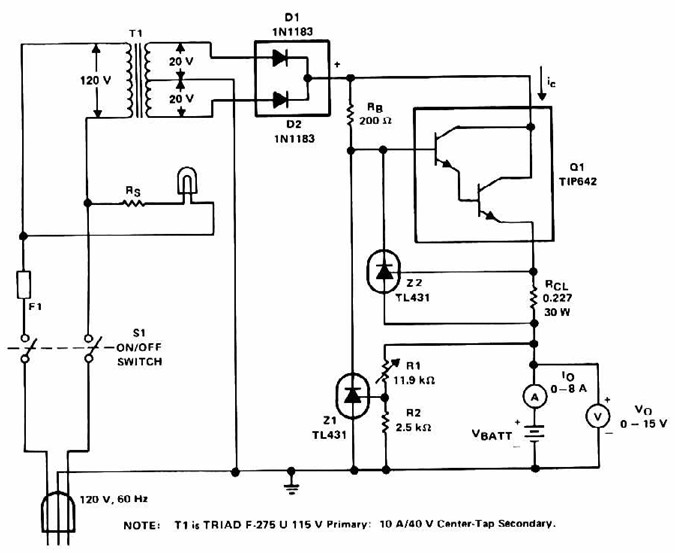
lead acid battery charger with current limit
Lead Acid Battery Charger with current limit power supply. Refer to the specified page for an explanation of the related circuit diagram.
The lead-acid battery charger with a current limit power supply is designed to safely charge lead-acid batteries while preventing...

Automatic Charger with CD4541
The circuit is capable of supplying either a trickle (50 mA) or high-current (1-A) charge. You can select either charging method or an automatic mode that will first trickle charge a battery if it is particularly low before switching to...

Lithium battery charger schematic circuit design using LTM8061 IC
A simple and efficient lithium battery charger and monitoring system can be designed using the LTM8061 integrated circuit from Linear Technology. The LTM8061 is a high-efficiency 32V, 2A module standalone lithium battery charger optimized for one- and two-cell packs, with...

24v 7ah lead acid battery charger
This lead-acid battery charger circuit is designed based on a request from Mr. Devdas C. His requirement was for a circuit to charge two 12V/7AH lead-acid batteries connected in series. However, the number of cells in each 12V battery was...
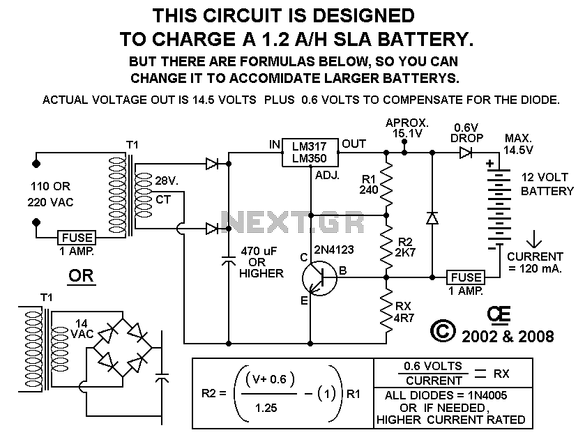
Battery Charger
Using this circuit will give good charging results to the gel cell battery used in the metal detector or any other similar and smaller type battery. This charger is both current and voltage regulated. The output is not short circuit...

Battery charger
A diac is utilized in the gate circuit to enable operation for the signal applied to the gate. R1 sets a threshold level for triggering the triac. C3 and R4 are chosen to restrict the maximum charging current, forming a...

Lead Acid Battery Charger III
This high-performance circuit first quickly starts (and holds) the charge at 2 amp, but as the voltage rises the current will consequently decrease. When the current falls below 150mA, the charger automatically switches to a lower 'Float' voltage to prevent...

Lithium battery charging constant current circuit diagram
As illustrated in the figure, the lithium battery charging control board employs a constant current charging mechanism. The components Q1, R1, W1, and TL431 form a precision adjustable voltage regulator circuit. The components Q2, W2, and R2 create an adjustable...

Battery charger circuit Schematic Diagram
This charger is based on a charging voltage of 2.4 volts per cell, in accordance with most manufacturers' recommendations. This circuit pulses the battery with 14.4 volts (6 cells x 2.4 volts per cell) at a rate of 120 Hz....